
Page 157 - Shale Shakers Drilling Fluid Systems
P. 157
140 SHALE SHAKERS AND DRILLING FLUID SYSTEMS
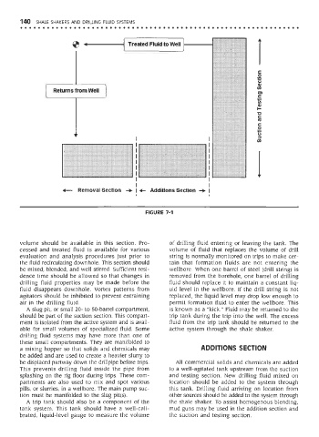
FIGURE 7-1
volume should be available in this section. Pro- of drilling fluid entering or leaving the tank. The
cessed and treated fluid is available for various volume of fluid that replaces the volume of drill
evaluation and analysis procedures just prior to string is normally monitored on trips to make cer-
the fluid recirculating downhole. This section should tain that formation fluids are not entering the
be mixed, blended, and well stirred. Sufficient resi- wellbore. When one barrel of steel (drill string) is
dence time should be allowed so that changes in removed from the borehole, one barrel of drilling
drilling fluid properties may be made before the fluid should replace it to maintain a constant liq-
fluid disappears downhole. Vortex patterns from uid level in the wellbore. If the drill string is not
agitators should be inhibited to prevent entraining replaced, the liquid level may drop low enough to
air in the drilling fluid. permit formation fluid to enter the wellbore. This
A slug pit, or small 20- to 50-barrel compartment, is known as a "kick." Fluid may be returned to the
should be part of the suction section. This compart- trip tank during the trip into the well. The excess
ment is isolated from the active system and is avail- fluid from the trip tank should be returned to the
able for small volumes of specialized fluid. Some active system through the shale shaker.
drilling fluid systems may have more than one of
these small compartments. They are manifolded to
a mixing hopper so that solids and chemicals may ADDITIONS SECTION
be added and are used to create a heavier slurry to
be displaced partway down the drillpipe before trips. All commercial solids and chemicals are added
This prevents drilling fluid inside the pipe from to a well-agitated tank upstream from the suction
splashing on the rig floor during trips. These com- and testing section. New drilling fluid mixed on
partments are also used to mix and spot various location should be added to the system through
pills, or slurries, in a wellbore. The main pump suc- this tank. Drilling fluid arriving on location from
tion must be manifolded to the slug pit(s). other sources should be added to the system through
A trip tank should also be a component of the the shale shaker. To assist homogenous blending,
tank system. This tank should have a well-cali- mud guns may be used in the addition section and
brated, liquid-level gauge to measure the volume the suction and testing section.