
Page 135 - Shigley's Mechanical Engineering Design
P. 135
bud29281_ch03_071-146.qxd 11/24/09 3:02PM Page 110 ntt 203:MHDQ196:bud29281:0073529281:bud29281_pagefiles:
110 Mechanical Engineering Design
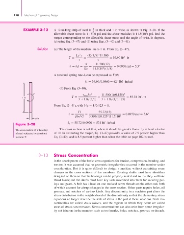
EXAMPLE 3–12 A 12-in-long strip of steel is 1 in thick and 1 in wide, as shown in Fig. 3–28. If the
8
6
allowable shear stress is 11 500 psi and the shear modulus is 11.5(10 ) psi, find the
torque corresponding to the allowable shear stress and the angle of twist, in degrees,
(a) using Eq. (3–47) and (b) using Eqs. (3–40) and (3–41).
Solution (a) The length of the median line is 1 in. From Eq. (3–47),
2
2
Lc τ (1)(1/8) 11 500
T = = = 59.90 lbf · in
3 3
τl 11 500(12)
θ = θ 1 l = = = 0.0960 rad = 5.5°
6
Gc 11.5(10 )(1/8)
A torsional spring rate k t can be expressed as T/θ:
k t = 59.90/0.0960 = 624 lbf · in/rad
(b) From Eq. (3–40),
T τ max bc 2 11 500(1)(0.125) 2
1 in T = = = 55.72 lbf · in
3 + 1.8/(b/c) 3 + 1.8/(1/0.125)
From Eq. (3–41), with b/c = 1/0.125 = 8,
Tl 55.72(12)
θ = = = 0.0970 rad = 5.6°
βbc G 0.307(1)0.125 (11.5)10 6
3
3
1 in
8
Figure 3–28 k t = 55.72/0.0970 = 574 lbf · in/rad
The cross-section of a thin strip The cross section is not thin, where b should be greater than c by at least a factor
of steel subjected to a torsional of 10. In estimating the torque, Eq. (3–47) provides a value of 7.5 percent higher than
moment T. Eq. (3–40), and is 8.5 percent higher than when the table on page 102 is used.
3–13 Stress Concentration
In the development of the basic stress equations for tension, compression, bending, and
torsion, it was assumed that no geometric irregularities occurred in the member under
consideration. But it is quite difficult to design a machine without permitting some
changes in the cross sections of the members. Rotating shafts must have shoulders
designed on them so that the bearings can be properly seated and so that they will take
thrust loads; and the shafts must have key slots machined into them for securing pul-
leys and gears. A bolt has a head on one end and screw threads on the other end, both
of which account for abrupt changes in the cross section. Other parts require holes, oil
grooves, and notches of various kinds. Any discontinuity in a machine part alters the
stress distribution in the neighborhood of the discontinuity so that the elementary stress
equations no longer describe the state of stress in the part at these locations. Such dis-
continuities are called stress raisers, and the regions in which they occur are called
areas of stress concentration. Stress concentrations can also arise from some irregular-
ity not inherent in the member, such as tool marks, holes, notches, grooves, or threads.