
Page 133 - Shigley's Mechanical Engineering Design
P. 133
bud29281_ch03_071-146.qxd 11/24/09 3:02PM Page 108 ntt 203:MHDQ196:bud29281:0073529281:bud29281_pagefiles:
108 Mechanical Engineering Design
Figure 3–25
The depicted cross section is ds
elliptical, but the section need r
1
not be symmetrical nor of dA = rds
m 2
constant thickness. t
Median line
where L m is the length of the section median line. These equations presume the buck-
ling of the tube is prevented by ribs, stiffeners, bulkheads, and so on, and that the
stresses are below the proportional limit.
1
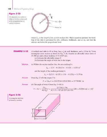
EXAMPLE 3–10 A welded steel tube is 40 in long, has a -in wall thickness, and a 2.5-in by 3.6-in
8
rectangular cross section as shown in Fig. 3–26. Assume an allowable shear stress of
6
11 500 psi and a shear modulus of 11.5(10 ) psi.
(a) Estimate the allowable torque T.
(b) Estimate the angle of twist due to the torque.
Solution (a) Within the section median line, the area enclosed is
A m = (2.5 − 0.125)(3.6 − 0.125) = 8.253 in 2
and the length of the median perimeter is
L m = 2[(2.5 − 0.125) + (3.6 − 0.125)] = 11.70 in
Answer From Eq. (3–45) the torque T is
T = 2A m tτ = 2(8.253)0.125(11 500) = 23 730 lbf · in
Answer (b) The angle of twist θ from Eq. (3–46) is
TL m 23 730(11.70)
θ = θ 1 l = l = (40) = 0.0284 rad = 1.62 ◦
2
6
2
4GA t 4(11.5 × 10 )(8.253 )(0.125)
m
Figure 3–26
A rectangular steel tube
produced by welding.
1 in
8
40 in
2.5 in
3.6 in