Page 128 - Shigley's Mechanical Engineering Design
P. 128

bud29281_ch03_071-146.qxd  11/24/09  3:01PM  Page 103 ntt 203:MHDQ196:bud29281:0073529281:bud29281_pagefiles:


                                                                                             Load and Stress Analysis  103
                                               where  H = power, hp
                                                      T = torque, lbf · in
                                                      n = shaft speed, rev/min
                                                      F = force, lbf
                                                      V = velocity, ft/min
                                               When SI units are used, the equation is

                                                                              H = Tω                           (3–43)
                                               where  H = power, W
                                                      T = torque, N · m
                                                      ω = angular velocity, rad/s
                                               The torque T corresponding to the power in watts is given approximately by

                                                                                    H
                                                                            T = 9.55                           (3–44)
                                                                                     n
                                               where n is in revolutions per minute.


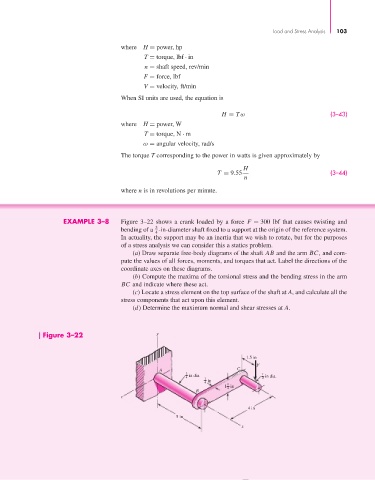
                             EXAMPLE 3–8       Figure 3–22 shows a crank loaded by a force  F = 300 lbf that causes twisting and
                                                         3
                                               bending of a  -in-diameter shaft fixed to a support at the origin of the reference system.
                                                         4
                                               In actuality, the support may be an inertia that we wish to rotate, but for the purposes
                                               of a stress analysis we can consider this a statics problem.
                                                  (a) Draw separate free-body diagrams of the shaft AB and the arm BC, and com-
                                               pute the values of all forces, moments, and torques that act. Label the directions of the
                                               coordinate axes on these diagrams.
                                                  (b) Compute the maxima of the torsional stress and the bending stress in the arm
                                               BC and indicate where these act.
                                                  (c) Locate a stress element on the top surface of the shaft at A, and calculate all the
                                               stress components that act upon this element.
                                                  (d) Determine the maximum normal and shear stresses at A.


                       Figure 3–22                        y


                                                                                     1.5 in
                                                                                         F
                                                           A                       C
                                                                   3  in dia.             1  in dia.
                                                                   4                      2
                                                                         1  in
                                                                         4      1
                                                                               1 in
                                                                                4
                                                                      B
                                               z
                                                                                      4 in
                                                                5 in
                                                                                    x
   123   124   125   126   127   128   129   130   131   132   133