
Page 126 - Shigley's Mechanical Engineering Design
P. 126
bud29281_ch03_071-146.qxd 11/24/09 3:01PM Page 101 ntt 203:MHDQ196:bud29281:0073529281:bud29281_pagefiles:
Load and Stress Analysis 101
3–12 Torsion
Any moment vector that is collinear with an axis of a mechanical element is called a
torque vector, because the moment causes the element to be twisted about that axis. A
bar subjected to such a moment is also said to be in torsion.
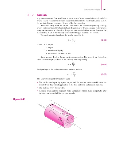
As shown in Fig. 3–21, the torque T applied to a bar can be designated by drawing
arrows on the surface of the bar to indicate direction or by drawing torque-vector arrows
along the axes of twist of the bar. Torque vectors are the hollow arrows shown on the
x axis in Fig. 3–21. Note that they conform to the right-hand rule for vectors.
The angle of twist, in radians, for a solid round bar is
Tl
θ = (3–35)
GJ
where T = torque
l = length
G = modulus of rigidity
J = polar second moment of area
Shear stresses develop throughout the cross section. For a round bar in torsion,
these stresses are proportional to the radius ρ and are given by
Tρ
τ = (3–36)
J
Designating r as the radius to the outer surface, we have
Tr
τ max = (3–37)
J
The assumptions used in the analysis are:
• The bar is acted upon by a pure torque, and the sections under consideration are
remote from the point of application of the load and from a change in diameter.
• The material obeys Hooke’s law.
• Adjacent cross sections originally plane and parallel remain plane and parallel after
twisting, and any radial line remains straight.
Figure 3–21
T
A l
y
dx
B
T
C
r
B'
O
C'
z x