Page 122 - Shigley's Mechanical Engineering Design
P. 122

bud29281_ch03_071-146.qxd  12/02/2009  4:14 pm  Page 97 pinnacle s-171:Desktop Folder:Temp Work:Don't Delete (Jobs):MHDQ196/Budynas:


                                                                                               Load and Stress Analysis  97
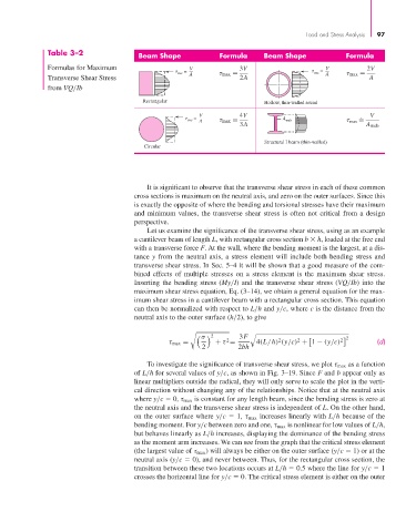
                       Table 3–2                Beam Shape             Formula     Beam Shape             Formula

                       Formulas for Maximum                   V             3V                      V          2V
                                                             =                                     =
                                                           avc  A       max =                    avc  A     max =
                       Transverse Shear Stress                              2A                                  A
                       from VQ/Ib
                                                 Rectangular
                                                                                   Hollow, thin-walled round
                                                                 V          4V                                  V
                                                                =                       A web                 .
                                                              avc  A    max =                               max =
                                                                            3A                                 A web
                                                                                   Structural I beam (thin-walled)
                                                  Circular


                                                  It is significant to observe that the transverse shear stress in each of these common
                                               cross sections is maximum on the neutral axis, and zero on the outer surfaces. Since this
                                               is exactly the opposite of where the bending and torsional stresses have their maximum
                                               and minimum values, the transverse shear stress is often not critical from a design
                                               perspective.
                                                  Let us examine the significance of the transverse shear stress, using as an example
                                               a cantilever beam of length L, with rectangular cross section b   h, loaded at the free end
                                               with a transverse force F. At the wall, where the bending moment is the largest, at a dis-
                                               tance y from the neutral axis, a stress element will include both bending stress and
                                               transverse shear stress. In Sec. 5–4 it will be shown that a good measure of the com-
                                               bined effects of multiple stresses on a stress element is the maximum shear stress.
                                               Inserting the bending stress (My/I) and the transverse shear stress (VQ/Ib) into the
                                               maximum shear stress equation, Eq. (3–14), we obtain a general equation for the max-
                                               imum shear stress in a cantilever beam with a rectangular cross section. This equation
                                               can then be normalized with respect to L/h and y/c, where c is the distance from the
                                               neutral axis to the outer surface (h/2), to give


                                                                 σ          3F                             2
                                                                    2
                                                                        2
                                                                                       2
                                                                                            2
                                                        τ max =      + τ =       4(L/h) (y/c) + 1 − (y/c) 2       (d)
                                                                  2         2bh
                                                  To investigate the significance of transverse shear stress, we plot τ max as a function
                                               of L/h for several values of y/c, as shown in Fig. 3–19. Since F and b appear only as
                                               linear multipliers outside the radical, they will only serve to scale the plot in the verti-
                                               cal direction without changing any of the relationships. Notice that at the neutral axis
                                               where y/c   0, τ max is constant for any length beam, since the bending stress is zero at
                                               the neutral axis and the transverse shear stress is independent of L. On the other hand,
                                               on the outer surface where y/c   1, τ max increases linearly with L/h because of the
                                               bending moment. For y/c between zero and one, τ max is nonlinear for low values of L/h,
                                               but behaves linearly as L/h increases, displaying the dominance of the bending stress
                                               as the moment arm increases. We can see from the graph that the critical stress element
                                               (the largest value of τ max ) will always be either on the outer surface (y/c   1) or at the
                                               neutral axis (y/c   0), and never between. Thus, for the rectangular cross section, the
                                               transition between these two locations occurs at L/h   0.5 where the line for y/c   1
                                               crosses the horizontal line for y/c   0. The critical stress element is either on the outer
   117   118   119   120   121   122   123   124   125   126   127