
Page 117 - Shigley's Mechanical Engineering Design
P. 117
bud29281_ch03_071-146.qxd 11/24/09 3:01PM Page 92 ntt 203:MHDQ196:bud29281:0073529281:bud29281_pagefiles:
92 Mechanical Engineering Design
Two-Plane Bending
Quite often, in mechanical design, bending occurs in both xy and xz planes. Considering
cross sections with one or two planes of symmetry only, the bending stresses are given by
M z y M y z
σ x =− + (3–27)
I z I y
where the first term on the right side of the equation is identical to Eq. (3–24), M y is
the bending moment in the xz plane (moment vector in y direction), z is the distance
from the neutral y axis, and I y is the second area moment about the y axis.
For noncircular cross sections, Eq. (3–27) is the superposition of stresses caused
by the two bending moment components. The maximum tensile and compressive bend-
ing stresses occur where the summation gives the greatest positive and negative stresses,
respectively. For solid circular cross sections, all lateral axes are the same and the plane
containing the moment corresponding to the vector sum of M z and M y contains the
maximum bending stresses. For a beam of diameter d the maximum distance from the
4
neutral axis is d/2, and from Table A–18, I = πd /64. The maximum bending stress for
a solid circular cross section is then
2 1/2
2
Mc (M + M ) (d/2) 32 2 2 1/2
z
y
σ m = = 4 = 3 (M + M ) (3–28)
y
z
I πd /64 πd
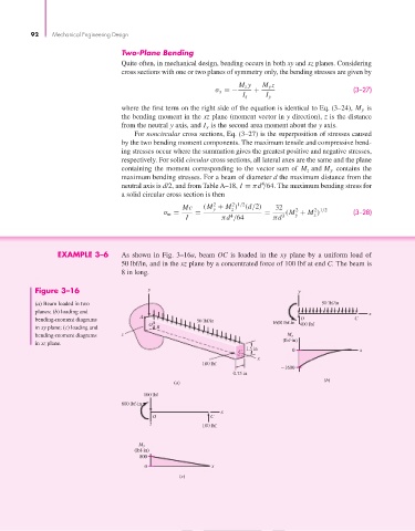
EXAMPLE 3–6 As shown in Fig. 3–16a, beam OC is loaded in the xy plane by a uniform load of
50 lbf/in, and in the xz plane by a concentrated force of 100 lbf at end C. The beam is
8 in long.
Figure 3–16 y y
(a) Beam loaded in two 50 lbf/in
planes; (b) loading and x
A
bending-moment diagrams 50 lbf/in O C
O 1600 lbf-in 400 lbf
in xy plane; (c) loading and B
bending-moment diagrams z M z
(lbf-in)
in xz plane.
1.5 in
C 0 x
x
100 lbf
1600
0.75 in
(b)
(a)
100 lbf
800 lbf-in
x
O C
z 100 lbf
M y
(lbf-in)
800
0 x
(c)