Page 115 - Shigley's Mechanical Engineering Design
P. 115

bud29281_ch03_071-146.qxd  11/26/09  5:56PM  Page 90 ntt G4 Mac OS 9.2:Desktop Folder:MHDQ196/Budynas:


                 90    Mechanical Engineering Design
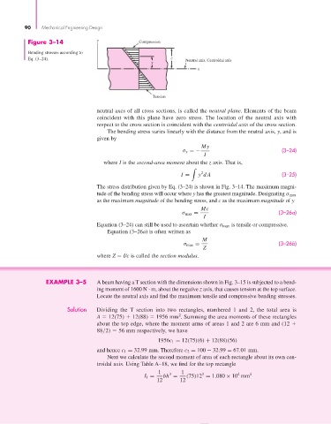
                  Figure 3–14             y              Compression

                  Bending stresses according to
                  Eq. (3–24).                                       c    Neutral axis, Centroidal axis
                                                             y
                                                                             x


                                                             Tension


                                          neutral axes of all cross sections, is called the neutral plane. Elements of the beam
                                          coincident with this plane have zero stress.  The location of the neutral axis with
                                          respect to the cross section is coincident with the centroidal axis of the cross section.
                                              The bending stress varies linearly with the distance from the neutral axis, y, and is
                                          given by
                                                                              My
                                                                        σ x =−                             (3–24)
                                                                               I
                                            where I is the second-area moment about the z axis. That is,

                                                                              2
                                                                       I =   y dA                          (3–25)
                                          The stress distribution given by Eq. (3–24) is shown in Fig. 3–14. The maximum magni-
                                          tude of the bending stress will occur where y has the greatest magnitude. Designating σ max
                                          as the maximum magnitude of the bending stress, and c as the maximum magnitude of y
                                                                              Mc
                                                                        σ max =                          (3–26a)
                                                                               I
                                          Equation (3–24) can still be used to ascertain whether σ max is tensile or compressive.
                                              Equation (3–26a) is often written as
                                                                               M
                                                                        σ max =                          (3–26b)
                                                                               Z
                                          where Z = I/c is called the section modulus.


                        EXAMPLE 3–5       A beam having a T section with the dimensions shown in Fig. 3–15 is subjected to a bend-
                                          ing moment of 1600 N · m, about the negative z axis, that causes tension at the top surface.
                                          Locate the neutral axis and find the maximum tensile and compressive bending stresses.
                                Solution  Dividing the  T section into two rectangles, numbered 1 and 2, the total area is
                                                                       2
                                          A   12(75)   12(88)   1956 mm . Summing the area moments of these rectangles
                                          about the top edge, where the moment arms of areas 1 and 2 are 6 mm and (12
                                          88/2)   56 mm respectively, we have
                                                               1956c 1 = 12(75)(6) + 12(88)(56)

                                          and hence c 1 = 32.99 mm. Therefore c 2 = 100 − 32.99 = 67.01 mm.
                                              Next we calculate the second moment of area of each rectangle about its own cen-
                                          troidal axis. Using Table A–18, we find for the top rectangle
                                                               1   3   1       3           4   4
                                                           I 1 =  bh =   (75)12 = 1.080 × 10 mm
                                                               12      12
   110   111   112   113   114   115   116   117   118   119   120