
Page 110 - Shigley's Mechanical Engineering Design
P. 110
bud29281_ch03_071-146.qxd 11/24/09 3:01PM Page 85 ntt 203:MHDQ196:bud29281:0073529281:bud29281_pagefiles:
Load and Stress Analysis 85
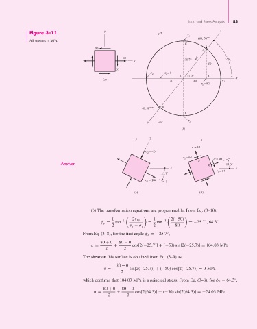
Figure 3–11 y cw x
1
cw
(80, 50 )
All stresses in MPa.
E
50 A
80 64 2
x 38.7° p
50
50
2 y = 0
C 51.3° D
(a)
40 40 1
= 80
x
(0, 50 ccw ) B
F
y ccw 2
(b)
y 2 y
= 40
= –24
2
= 64
2 = 40
Answer F 19.3°
x E x
= 64
1
25.7°
= 104 1
1
(c) (d)
(b) The transformation equations are programmable. From Eq. (3–10),
1 −1 2τ xy 1 −1 2(−50)
◦
φ p = tan = tan =−25.7 , 64.3 ◦
2 σ x − σ y 2 80
From Eq. (3–8), for the first angle φ p =−25.7 ,
◦
80 + 0 80 − 0
σ = + cos[2(−25.7)] + (−50) sin[2(−25.7)] = 104.03 MPa
2 2
The shear on this surface is obtained from Eq. (3–9) as
80 − 0
τ =− sin[2(−25.7)] + (−50) cos[2(−25.7)] = 0MPa
2
◦
which confirms that 104.03 MPa is a principal stress. From Eq. (3–8), for φ p = 64.3 ,
80 + 0 80 − 0
σ = + cos[2(64.3)] + (−50) sin[2(64.3)] =−24.03 MPa
2 2