Page 108 - Shigley's Mechanical Engineering Design
P. 108

bud29281_ch03_071-146.qxd  11/24/09  3:01PM  Page 83 ntt 203:MHDQ196:bud29281:0073529281:bud29281_pagefiles:


                                                                                              Load and Stress Analysis  83
                       Figure 3–10                cw                   x
                                                                     (   –   )
                       Mohr’s circle diagram.         y               x  y       –
                                                                               x  y
                                                                               2
                                                                      F


                                                    y
                                                       B                                H
                                                          (  ,   xy cw )
                                                           y
                                                 xy
                                                    E                       2              D
                                                 O    2    y          C                   x    1
                                                                                                      xy
                                                                             x  –   y

                                                                            2    2       A        2  p
                                                                                 2         ccw )
                                                                                         x
                                                                                        (  ,   xy
                                                                               +   xy
                                                                                                  x
                                                              +         G
                                                  ccw       x  y
                                                             2


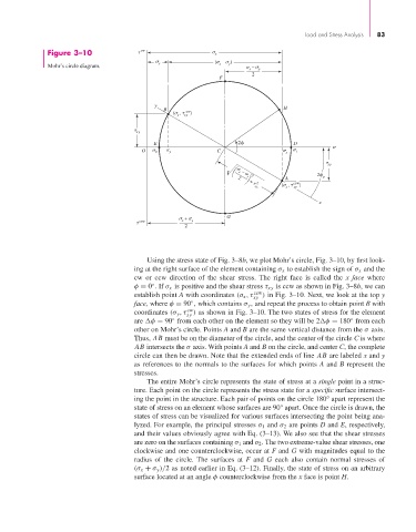
                                                  Using the stress state of Fig. 3–8b, we plot Mohr’s circle, Fig. 3–10, by first look-
                                               ing at the right surface of the element containing σ x to establish the sign of σ x and the
                                               cw or ccw direction of the shear stress.  The right face is called the  x face where
                                                    ◦
                                               φ = 0 . If σ x is positive and the shear stress τ xy is ccw as shown in Fig. 3–8b, we can
                                               establish point A with coordinates (σ x ,τ ccw ) in Fig. 3–10. Next, we look at the top y
                                                                                xy
                                               face, where φ = 90 , which contains σ y , and repeat the process to obtain point B with
                                                              ◦
                                                              cw
                                               coordinates (σ y ,τ ) as shown in Fig. 3–10. The two states of stress for the element
                                                             xy
                                                                                                           ◦
                                               are  φ = 90 from each other on the element so they will be 2 φ = 180 from each
                                                         ◦
                                               other on Mohr’s circle. Points A and B are the same vertical distance from the σ axis.
                                               Thus, AB must be on the diameter of the circle, and the center of the circle C is where
                                               AB intersects the σ axis. With points A and B on the circle, and center C, the complete
                                               circle can then be drawn. Note that the extended ends of line AB are labeled x and y
                                               as references to the normals to the surfaces for which points A and B represent the
                                               stresses.
                                                  The entire Mohr’s circle represents the state of stress at a single point in a struc-
                                               ture. Each point on the circle represents the stress state for a specific surface intersect-
                                               ing the point in the structure. Each pair of points on the circle 180° apart represent the
                                               state of stress on an element whose surfaces are 90° apart. Once the circle is drawn, the
                                               states of stress can be visualized for various surfaces intersecting the point being ana-
                                               lyzed. For example, the principal stresses σ 1 and σ 2 are points D and E, respectively,
                                               and their values obviously agree with Eq. (3–13). We also see that the shear stresses
                                               are zero on the surfaces containing σ 1 and σ 2 . The two extreme-value shear stresses, one
                                               clockwise and one counterclockwise, occur at F and G with magnitudes equal to the
                                               radius of the circle.  The surfaces at  F and  G each also contain normal stresses of
                                               (σ x + σ y )/2 as noted earlier in Eq. (3–12). Finally, the state of stress on an arbitrary
                                               surface located at an angle φ counterclockwise from the x face is point H.
   103   104   105   106   107   108   109   110   111   112   113