
Page 104 - Shigley's Mechanical Engineering Design
P. 104
bud29281_ch03_071-146.qxd 11/24/09 3:01PM Page 79 ntt 203:MHDQ196:bud29281:0073529281:bud29281_pagefiles:
Load and Stress Analysis 79
Answer which yields R 1 = 80 lbf.
From Eq. (3) we get
2
2
−M 1 (1) + 80(10) − 10(10 − 3) + 10(10 − 7) − 240(1) = 0
Answer which yields M 1 = 160 lbf · in.
Figures 3–6b and c show the shear-force and bending-moment diagrams. Note that
−1 −1
the impulse terms in Eq. (2), −M 1 x and −240 x − 10 , are physically not forces
and are not shown in the V diagram. Also note that both the M 1 and 240 lbf · in
moments are counterclockwise and negative singularity functions; however, by the con-
vention shown in Fig. 3–2 the M 1 and 240 lbf · in are negative and positive bending
moments, respectively, which is reflected in Fig. 3–6c.
3–4 Stress
When an internal surface is isolated as in Fig. 3–2b, the net force and moment acting on
the surface manifest themselves as force distributions across the entire area. The force
distribution acting at a point on the surface is unique and will have components in the
normal and tangential directions called normal stress and tangential shear stress,
respectively. Normal and shear stresses are labeled by the Greek symbols σ and τ,
respectively. If the direction of σ is outward from the surface it is considered to be a ten-
sile stress and is a positive normal stress. If σ is into the surface it is a compressive stress
and commonly considered to be a negative quantity. The units of stress in U.S.
Customary units are pounds per square inch (psi). For SI units, stress is in newtons per
2
2
square meter (N/m ); 1N/m = 1 pascal (Pa).
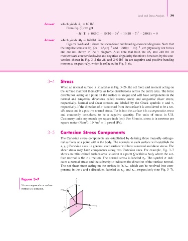
3–5 Cartesian Stress Components
The Cartesian stress components are established by defining three mutually orthogo-
nal surfaces at a point within the body. The normals to each surface will establish the
x, y, z Cartesian axes. In general, each surface will have a normal and shear stress. The
shear stress may have components along two Cartesian axes. For example, Fig. 3–7
shows an infinitesimal surface area isolation at a point Q within a body where the sur-
face normal is the x direction. The normal stress is labeled σ x . The symbol σ indi-
cates a normal stress and the subscript x indicates the direction of the surface normal.
The net shear stress acting on the surface is (τ x ) net which can be resolved into com-
ponents in the y and z directions, labeled as τ xy and τ xz , respectively (see Fig. 3–7).
Figure 3–7 y
Stress components on surface xy
normal to x direction. ( )
x net
Q x
xz x
z