Page 106 - Shigley's Mechanical Engineering Design
P. 106

bud29281_ch03_071-146.qxd  11/24/09  3:01PM  Page 81 ntt 203:MHDQ196:bud29281:0073529281:bud29281_pagefiles:


                                                                                              Load and Stress Analysis  81
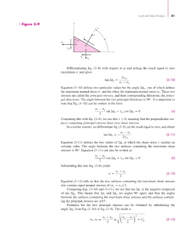
                       Figure 3–9                     y
                                                                     n


                                                 x
                                                       dy dy
                                                             ds ds
                                                    xy       dx
                                                             dx
                                                                              x
                                                             xy
                                                                 y
                                                  Differentiating Eq. (3–8) with respect to φ and setting the result equal to zero
                                               maximizes σ and gives
                                                                                    2τ xy
                                                                          tan 2φ p =                           (3–10)
                                                                                  σ x − σ y
                                               Equation (3–10) defines two particular values for the angle 2φ p , one of which defines
                                               the maximum normal stress σ 1 and the other, the minimum normal stress σ 2 . These two
                                               stresses are called the principal stresses, and their corresponding directions, the princi-
                                               pal directions. The angle between the two principal directions is 90°. It is important to
                                               note that Eq. (3–10) can be written in the form
                                                                    σ x − σ y
                                                                           sin 2φ p − τ xy cos 2φ p = 0           (a)
                                                                      2
                                               Comparing this with Eq. (3–9), we see that τ = 0, meaning that the perpendicular sur-
                                               faces containing principal stresses have zero shear stresses.
                                                  In a similar manner, we differentiate Eq. (3–9), set the result equal to zero, and obtain
                                                                                   σ x − σ y
                                                                         tan 2φ s =−                           (3–11)
                                                                                     2τ xy
                                               Equation (3–11) defines the two values of 2φ s at which the shear stress τ reaches an
                                               extreme value. The angle between the two surfaces containing the maximum shear
                                               stresses is 90°. Equation (3–11) can also be written as

                                                                    σ x − σ y
                                                                           cos 2φ p + τ xy sin 2φ p = 0           (b)
                                                                      2
                                               Substituting this into Eq. (3–8) yields

                                                                                σ x + σ y
                                                                            σ =                                (3–12)
                                                                                   2
                                               Equation (3–12) tells us that the two surfaces containing the maximum shear stresses
                                               also contain equal normal stresses of (σ x + σ y )/2.
                                                  Comparing Eqs. (3–10) and (3–11), we see that tan 2φ s is the negative reciprocal
                                               of tan 2φ p . This means that 2φ s and 2φ p are angles 90° apart, and thus the angles
                                               between the surfaces containing the maximum shear stresses and the surfaces contain-
                                               ing the principal stresses are ±45 .
                                                                          ◦
                                                  Formulas for the two principal stresses can be obtained by substituting the
                                               angle 2φ p from Eq. (3–10) in Eq. (3–8). The result is

                                                                                            2

                                                                        σ x + σ y   σ x − σ y
                                                                                                 2
                                                                 σ 1 ,σ 2 =    ±              + τ xy           (3–13)
                                                                           2           2
   101   102   103   104   105   106   107   108   109   110   111