
Page 109 - Shigley's Mechanical Engineering Design
P. 109
bud29281_ch03_071-146.qxd 11/24/09 3:01PM Page 84 ntt 203:MHDQ196:bud29281:0073529281:bud29281_pagefiles:
84 Mechanical Engineering Design
At one time, Mohr’s circle was used graphically where it was drawn to scale very
accurately and values were measured by using a scale and protractor. Here, we are strictly
using Mohr’s circle as a visualization aid and will use a semigraphical approach, calculat-
ing values from the properties of the circle. This is illustrated by the following example.
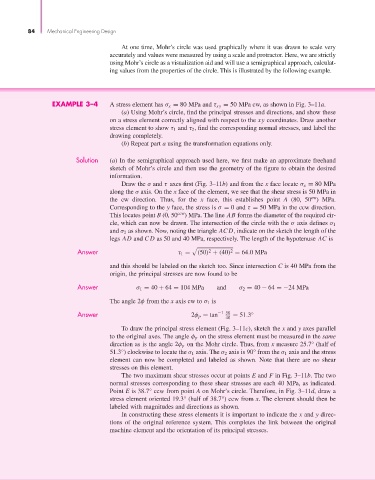
EXAMPLE 3–4 A stress element has σ x = 80 MPa and τ xy = 50 MPa cw, as shown in Fig. 3–11a.
(a) Using Mohr’s circle, find the principal stresses and directions, and show these
on a stress element correctly aligned with respect to the xy coordinates. Draw another
stress element to show τ 1 and τ 2 , find the corresponding normal stresses, and label the
drawing completely.
(b) Repeat part a using the transformation equations only.
Solution (a) In the semigraphical approach used here, we first make an approximate freehand
sketch of Mohr’s circle and then use the geometry of the figure to obtain the desired
information.
Draw the σ and τ axes first (Fig. 3–11b) and from the x face locate σ x = 80 MPa
along the σ axis. On the x face of the element, we see that the shear stress is 50 MPa in
cw
the cw direction. Thus, for the x face, this establishes point A (80, 50 ) MPa.
Corresponding to the y face, the stress is σ = 0 and τ = 50 MPa in the ccw direction.
This locates point B (0, 50 ccw ) MPa. The line AB forms the diameter of the required cir-
cle, which can now be drawn. The intersection of the circle with the σ axis defines σ 1
and σ 2 as shown. Now, noting the triangle AC D, indicate on the sketch the length of the
legs AD and CD as 50 and 40 MPa, respectively. The length of the hypotenuse AC is
Answer τ 1 = (50) + (40) = 64.0MPa
2
2
and this should be labeled on the sketch too. Since intersection C is 40 MPa from the
origin, the principal stresses are now found to be
Answer σ 1 = 40 + 64 = 104 MPa and σ 2 = 40 − 64 =−24 MPa
The angle 2φ from the x axis cw to σ 1 is
Answer 2φ p = tan −1 50 = 51.3 ◦
40
To draw the principal stress element (Fig. 3–11c), sketch the x and y axes parallel
to the original axes. The angle φ p on the stress element must be measured in the same
direction as is the angle 2φ p on the Mohr circle. Thus, from x measure 25.7° (half of
51.3°) clockwise to locate the σ 1 axis. The σ 2 axis is 90° from the σ 1 axis and the stress
element can now be completed and labeled as shown. Note that there are no shear
stresses on this element.
The two maximum shear stresses occur at points E and F in Fig. 3–11b. The two
normal stresses corresponding to these shear stresses are each 40 MPa, as indicated.
Point E is 38.7° ccw from point A on Mohr’s circle. Therefore, in Fig. 3–11d, draw a
stress element oriented 19.3° (half of 38.7°) ccw from x. The element should then be
labeled with magnitudes and directions as shown.
In constructing these stress elements it is important to indicate the x and y direc-
tions of the original reference system. This completes the link between the original
machine element and the orientation of its principal stresses.