Page 112 - Shigley's Mechanical Engineering Design
P. 112

bud29281_ch03_071-146.qxd  11/24/09  3:01PM  Page 87 ntt 203:MHDQ196:bud29281:0073529281:bud29281_pagefiles:


                                                                                              Load and Stress Analysis  87
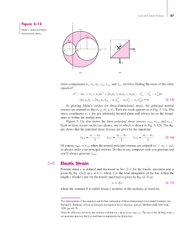
                       Figure 3–12


                       Mohr’s circles for three-           1/3
                       dimensional stress.

                                                               1/2
                                                     2/3
                                                                                    1/2


                                                   3       2            1
                                                                                            1

                                                                                      2

                                                          (a)                     (b)


                                               stress components σ x ,σ y ,σ z ,τ xy ,τ yz , and τ zx , involves finding the roots of the cubic
                                               equation 1
                                                                        2
                                                        3
                                                                                                          2
                                                                                                     2
                                                                                                2

                                                      σ − (σ x + σ y + σ z )σ + σ x σ y + σ x σ z + σ y σ z − τ xy  − τ − τ zx    σ
                                                                                                     yz
                                                                                  2     2      2
                                                         − σ x σ y σ z + 2τ xy τ yz τ zx − σ x τ − σ y τ − σ z τ xy  = 0  (3–15)
                                                                                        zx
                                                                                 yz
                                                  In plotting Mohr’s circles for three-dimensional stress, the principal normal
                                               stresses are ordered so that σ 1 ≥ σ 2 ≥ σ 3 . Then the result appears as in Fig. 3–12a. The
                                               stress coordinates σ, τ for any arbitrarily located plane will always lie on the bound-
                                               aries or within the shaded area.
                                                  Figure 3–12a also shows the three principal shear stresses τ 1/2 , τ 2/3 , and τ 1/3 . 2
                                               Each of these occurs on the two planes, one of which is shown in Fig. 3–12b. The fig-
                                               ure shows that the principal shear stresses are given by the equations
                                                                 σ 1 − σ 2       σ 2 − σ 3       σ 1 − σ 3
                                                           τ 1/2 =         τ 2/3 =         τ 1/3 =             (3–16)
                                                                   2                2               2
                                               Of course, τ max = τ 1/3 when the normal principal stresses are ordered (σ 1 >σ 2 >σ 3 ),
                                               so always order your principal stresses. Do this in any computer code you generate and
                                               you’ll always generate τ max .

                                       3–8     Elastic Strain
                                               Normal strain   is defined and discussed in Sec. 2–1 for the tensile specimen and is
                                               given by Eq. (2–2) as   = δ/l, where δ is the total elongation of the bar within the
                                               length l. Hooke’s law for the tensile specimen is given by Eq. (2–3) as
                                                                              σ = E                            (3–17)

                                               where the constant E is called Young’s modulus or the modulus of elasticity.


                                               1 For development of this equation and further elaboration of three-dimensional stress transformations see:
                                               Richard G. Budynas, Advanced Strength and Applied Stress Analysis, 2nd ed., McGraw-Hill, New York,
                                               1999, pp. 46–78.
                                               2 Note the difference between this notation and that for a shear stress, say, τ xy . The use of the shilling mark is
                                               not accepted practice, but it is used here to emphasize the distinction.
   107   108   109   110   111   112   113   114   115   116   117