
Page 114 - Shigley's Mechanical Engineering Design
P. 114
bud29281_ch03_071-146.qxd 11/24/09 3:01PM Page 89 ntt 203:MHDQ196:bud29281:0073529281:bud29281_pagefiles:
Load and Stress Analysis 89
For simple compression, Eq. (3–22) is applicable with F normally being consid-
ered a negative quantity. Also, a slender bar in compression may fail by buckling, and
this possibility must be eliminated from consideration before Eq. (3–22) is used. 3
Another type of loading that assumes a uniformly distributed stress is known as
direct shear. This occurs when there is a shearing action with no bending. An example
is the action on a piece of sheet metal caused by the two blades of tin snips. Bolts and
pins that are loaded in shear often have direct shear. Think of a cantilever beam with a
force pushing down on it. Now move the force all the way up to the wall so there is no
bending moment, just a force trying to shear the beam off the wall. This is direct shear.
Direct shear is usually assumed to be uniform across the cross section, and is given by
V
τ = (3–23)
A
where V is the shear force and A is the area of the cross section that is being sheared.
The assumption of uniform stress is not accurate, particularly in the vicinity where the
force is applied, but the assumption generally gives acceptable results.
3–10 Normal Stresses for Beams in Bending
The equations for the normal bending stresses in straight beams are based on the fol-
lowing assumptions.
• The beam is subjected to pure bending. This means that the shear force is zero, and
that no torsion or axial loads are present (for most engineering applications it is as-
sumed that these loads affect the bending stresses minimally).
• The material is isotropic and homogeneous.
• The material obeys Hooke’s law.
• The beam is initially straight with a cross section that is constant throughout the
beam length.
• The beam has an axis of symmetry in the plane of bending.
• The proportions of the beam are such that it would fail by bending rather than by
crushing, wrinkling, or sidewise buckling.
• Plane cross sections of the beam remain plane during bending.
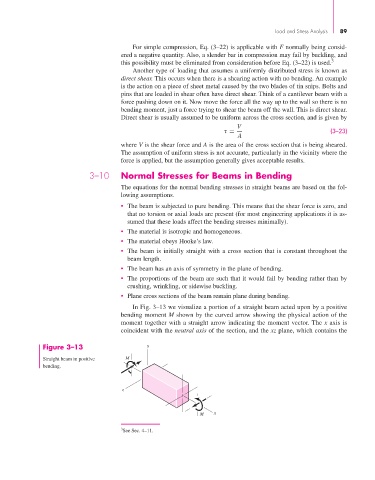
In Fig. 3–13 we visualize a portion of a straight beam acted upon by a positive
bending moment M shown by the curved arrow showing the physical action of the
moment together with a straight arrow indicating the moment vector. The x axis is
coincident with the neutral axis of the section, and the xz plane, which contains the
Figure 3–13 y
Straight beam in positive M
bending.
z
M x
3 See Sec. 4–11.