
Page 105 - Shigley's Mechanical Engineering Design
P. 105
bud29281_ch03_071-146.qxd 11/24/09 3:01PM Page 80 ntt 203:MHDQ196:bud29281:0073529281:bud29281_pagefiles:
80 Mechanical Engineering Design
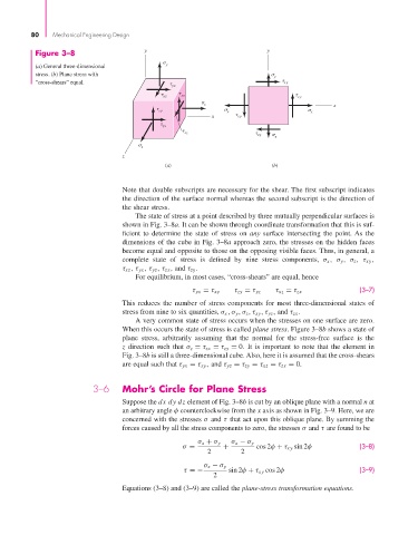
Figure 3–8 y y
(a) General three-dimensional y
stress. (b) Plane stress with
y
“cross-shears” equal. yx xy
xy
yz xy
x
x
zy x x
x xy
zx
xz xy y
z
z
(a) (b)
Note that double subscripts are necessary for the shear. The first subscript indicates
the direction of the surface normal whereas the second subscript is the direction of
the shear stress.
The state of stress at a point described by three mutually perpendicular surfaces is
shown in Fig. 3–8a. It can be shown through coordinate transformation that this is suf-
ficient to determine the state of stress on any surface intersecting the point. As the
dimensions of the cube in Fig. 3–8a approach zero, the stresses on the hidden faces
become equal and opposite to those on the opposing visible faces. Thus, in general, a
complete state of stress is defined by nine stress components, σ x ,σ y ,σ z ,τ xy ,
τ xz ,τ yx ,τ yz ,τ zx , and τ zy .
For equilibrium, in most cases, “cross-shears” are equal, hence
(3–7)
τ yx = τ xy τ zy = τ yz τ xz = τ zx
This reduces the number of stress components for most three-dimensional states of
stress from nine to six quantities, σ x ,σ y ,σ z ,τ xy ,τ yz , and τ zx .
A very common state of stress occurs when the stresses on one surface are zero.
When this occurs the state of stress is called plane stress. Figure 3–8b shows a state of
plane stress, arbitrarily assuming that the normal for the stress-free surface is the
z direction such that σ z = τ zx = τ zy = 0. It is important to note that the element in
Fig. 3–8b is still a three-dimensional cube. Also, here it is assumed that the cross-shears
are equal such that τ yx = τ xy , and τ yz = τ zy = τ xz = τ zx = 0.
3–6 Mohr’s Circle for Plane Stress
Suppose the dx dy dz element of Fig. 3–8b is cut by an oblique plane with a normal n at
an arbitrary angle φ counterclockwise from the x axis as shown in Fig. 3–9. Here, we are
concerned with the stresses σ and τ that act upon this oblique plane. By summing the
forces caused by all the stress components to zero, the stresses σ and τ are found to be
σ x + σ y σ x − σ y
σ = + cos 2φ + τ xy sin 2φ (3–8)
2 2
σ x − σ y
τ =− sin 2φ + τ xy cos 2φ (3–9)
2
Equations (3–8) and (3–9) are called the plane-stress transformation equations.