Page 100 - Shigley's Mechanical Engineering Design
P. 100

bud29281_ch03_071-146.qxd  11/24/09  3:01PM  Page 75 ntt 203:MHDQ196:bud29281:0073529281:bud29281_pagefiles:


                                                                                              Load and Stress Analysis  75
                                               an equal but opposite torsional moment. The center of rotation relative to the bolts lies at
                                               the centroid of the bolt cross-sectional areas. Thus if the bolt areas are equal: the center

                                                                                                   2
                                                                                                          2
                                               of rotation is at the center of the four bolts, a distance of  (4/2) + (5/2) = 3.202 in
                                               from each bolt; the bolt forces are equal (R E = R F = R H = R I = R), and each bolt force
                                               is perpendicular to the line from the bolt to the center of rotation. This gives a net torque
                                               from the four bolts of 4R(3.202) = 720. Thus, R E = R F = R H = R I = 56.22 lbf.


                                       3–2     Shear Force and Bending Moments in Beams

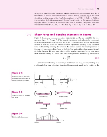
                                               Figure 3–2a shows a beam supported by reactions R 1 and R 2 and loaded by the con-
                                               centrated forces F 1 , F 2 , and F 3 . If the beam is cut at some section located at x = x 1 and
                                               the left-hand portion is removed as a free body, an internal shear force V and bending
                                               moment M must act on the cut surface to ensure equilibrium (see Fig. 3–2b). The shear
                                               force is obtained by summing the forces on the isolated section. The bending moment is
                                               the sum of the moments of the forces to the left of the section taken about an axis through
                                               the isolated section. The sign conventions used for bending moment and shear force in this
                                               book are shown in Fig. 3–3. Shear force and bending moment are related by the equation

                                                                                  dM
                                                                             V =                                (3–3)
                                                                                  dx
                                                  Sometimes the bending is caused by a distributed load q(x), as shown in Fig. 3–4;
                                               q(x) is called the load intensity with units of force per unit length and is positive in the


                       Figure 3–2              y                          y

                       Free-body diagram of simply-  F 1     F 2  F 3           F 1
                       supported beam with V and M                                V
                                                                        x                  x
                       shown in positive directions.                                   M
                                                   x 1                        x 1
                                                R 1                 R 2    R 1
                                                          (a)                     (b)

                       Figure 3–3

                       Sign conventions for bending
                                                    Positive bending     Negative bending
                       and shear.


                                                    Positive shear        Negative shear


                       Figure 3–4                y           q(x)
                       Distributed load on beam.
                                                                              x
   95   96   97   98   99   100   101   102   103   104   105