
Page 98 - Shigley's Mechanical Engineering Design
P. 98
bud29281_ch03_071-146.qxd 11/24/09 3:01PM Page 73 ntt 203:MHDQ196:bud29281:0073529281:bud29281_pagefiles:
Load and Stress Analysis 73
Free-Body Diagrams
We can greatly simplify the analysis of a very complex structure or machine by suc-
cessively isolating each element and studying and analyzing it by the use of free-body
diagrams. When all the members have been treated in this manner, the knowledge
obtained can be assembled to yield information concerning the behavior of the total sys-
tem. Thus, free-body diagramming is essentially a means of breaking a complicated
problem into manageable segments, analyzing these simple problems, and then, usually,
putting the information together again.
Using free-body diagrams for force analysis serves the following important purposes:
• The diagram establishes the directions of reference axes, provides a place to record
the dimensions of the subsystem and the magnitudes and directions of the known
forces, and helps in assuming the directions of unknown forces.
• The diagram simplifies your thinking because it provides a place to store one thought
while proceeding to the next.
• The diagram provides a means of communicating your thoughts clearly and unam-
biguously to other people.
• Careful and complete construction of the diagram clarifies fuzzy thinking by bringing
out various points that are not always apparent in the statement or in the geometry
of the total problem. Thus, the diagram aids in understanding all facets of the problem.
• The diagram helps in the planning of a logical attack on the problem and in setting
up the mathematical relations.
• The diagram helps in recording progress in the solution and in illustrating the
methods used.
• The diagram allows others to follow your reasoning, showing all forces.
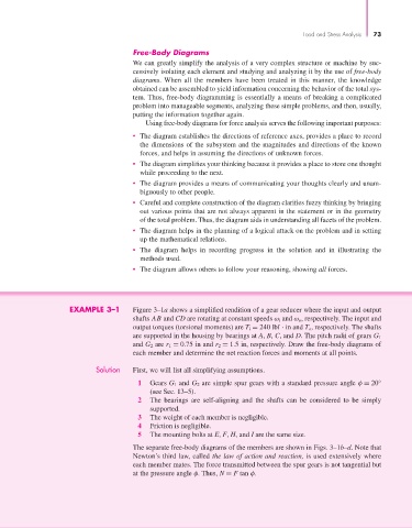
EXAMPLE 3–1 Figure 3–1a shows a simplified rendition of a gear reducer where the input and output
shafts AB and CD are rotating at constant speeds ω i and ω o, respectively. The input and
output torques (torsional moments) are T i = 240 lbf · in and T o, respectively. The shafts
are supported in the housing by bearings at A, B, C, and D. The pitch radii of gears G 1
and G 2 are r 1 = 0.75 in and r 2 = 1.5 in, respectively. Draw the free-body diagrams of
each member and determine the net reaction forces and moments at all points.
Solution First, we will list all simplifying assumptions.
1 Gears G 1 and G 2 are simple spur gears with a standard pressure angle φ = 20°
(see Sec. 13–5).
2 The bearings are self-aligning and the shafts can be considered to be simply
supported.
3 The weight of each member is negligible.
4 Friction is negligible.
5 The mounting bolts at E, F, H, and I are the same size.
The separate free-body diagrams of the members are shown in Figs. 3–1b–d. Note that
Newton’s third law, called the law of action and reaction, is used extensively where
each member mates. The force transmitted between the spur gears is not tangential but
at the pressure angle φ. Thus, N = F tan φ.