Page 102 - Shigley's Mechanical Engineering Design
P. 102

bud29281_ch03_071-146.qxd  11/30/2009  5:03 pm  Page 77 pinnacle 203:MHDQ196:bud29281:0073529281:bud29281_pagefiles:


                                                                                              Load and Stress Analysis  77
                                       3–3     Singularity Functions

                                               The four singularity functions defined in Table 3–1, using the angle brackets   , consti-
                                               tute a useful and easy means of integrating across discontinuities. By their use, general
                                               expressions for shear force and bending moment in beams can be written when the beam
                                               is loaded by concentrated moments or forces. As shown in the table, the concentrated
                                               moment and force functions are zero for all values of x not equal to a. The functions are
                                               undefined for values of x = a. Note that the unit step and ramp functions are zero only
                                               for values of x that are less than a. The integration properties shown in the table con-
                                               stitute a part of the mathematical definition too. The first two integrations of q(x) for
                                               V(x) and M(x) do not require constants of integration provided all loads on the beam
                                               are accounted for in q(x). The examples that follow show how these functions are used.


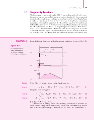
                             EXAMPLE 3–2       Derive the loading, shear-force, and bending-moment relations for the beam of Fig. 3–5a.

                       Figure 3–5                         y
                                                                      20 in
                       (a) Loading diagram for a
                                                                200 lbf  100 lbf
                       simply-supported beam.
                       (b) Shear-force diagram.          O
                                               (a)                                         x
                       (c) Bending-moment diagram.          4 in
                                                                 10 in
                                                        R                              R
                                                         1                              2
                                                      V (lbf)
                                                       210
                                               (b)      10                                 x
                                                        O
                                                       –90
                                                   M (lbf   in)

                                                       900
                                                       840

                                               (c)      O                                  x

                                    Solution   Using Table 3–1 and q(x) for the loading function, we find

                                     Answer             q = R 1  x  −1  − 200 x − 4  −1  − 100 x − 10  −1  + R 2  x − 20  −1  (1)
                                               Integrating successively gives


                                     Answer          V =    qdx = R 1  x  − 200 x − 4  − 100 x − 10  + R 2  x − 20  0  (2)
                                                                                                0
                                                                       0
                                                                                   0

                                                                       1
                                                                                    1
                                     Answer          M =    Vdx = R 1  x  − 200 x − 4  − 100 x − 10  + R 2  x − 20  1  (3)
                                                                                                 1

                                               Note that V   M   0 at x   0 .
                                                  The reactions  R 1 and  R 2 can be found by taking a summation of moments and
                                               forces as usual, or they can be found by noting that the shear force and bending moment
                                               must be zero everywhere except in the region 0 ≤ x ≤ 20 in. This means that Eq. (2)
   97   98   99   100   101   102   103   104   105   106   107