
Page 101 - Shigley's Mechanical Engineering Design
P. 101
bud29281_ch03_071-146.qxd 11/24/09 3:01PM Page 76 ntt 203:MHDQ196:bud29281:0073529281:bud29281_pagefiles:
76 Mechanical Engineering Design
positive y direction. It can be shown that differentiating Eq. (3–3) results in
2
dV d M
= = q (3–4)
dx dx 2
Normally the applied distributed load is directed downward and labeled w (e.g., see
Fig. 3–6). In this case, w =−q.
Equations (3–3) and (3–4) reveal additional relations if they are integrated. Thus,
if we integrate between, say, x A and x B , we obtain
V B x B
dV = V B − V A = qdx (3–5)
V A x A
which states that the change in shear force from A to B is equal to the area of the load-
ing diagram between x A and x B .
In a similar manner,
M B x B
dM = M B − M A = Vdx (3–6)
M A x A
which states that the change in moment from A to B is equal to the area of the shear-
force diagram between x A and x B .
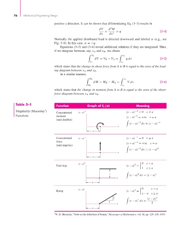
Table 3–1 Function Graph of f n (x) Meaning
†
Singularity (Macaulay ) –2 −2 = 0 x = a
Concentrated x – a x − a
Functions moment −2
x − a =±∞ x = a
(unit doublet)
−2 −1
x − a dx = x − a
x
a
−1
Concentrated x – a –1 x − a = 0 x = a
force −1
x − a =+∞ x = a
(unit impulse)
−1 0
x − a dx = x − a
x
a
0 0 x < a
x – a 0
Unit step x − a =
1 x ≥ a
1 0 1
x − a dx = x − a
x
a
1 0 x < a
x – a 1
Ramp x − a =
x − a x ≥ a
1 2
1 x − a
1 x − a dx =
x 2
a
† W. H. Macaulay, “Note on the deflection of beams,” Messenger of Mathematics, vol. 48, pp. 129–130, 1919.