
Page 99 - Shigley's Mechanical Engineering Design
P. 99
bud29281_ch03_071-146.qxd 11/24/09 3:01PM Page 74 ntt 203:MHDQ196:bud29281:0073529281:bud29281_pagefiles:
74 Mechanical Engineering Design
F F R
R E F
T o E R B E
B By z
G , T 240 lbf in R Bz
i
i
1 R Dz A y
A R
Dy R Ay
o D D R
G 2 5 in C 5 in R Cz Az x
R
H Cy H
C
R R
I I H
I
4 in 4 in
(a) Gear reducer (b) Gear box
1.5 in
R R By 1 in
Bz
T
0 N F
r R R Ay T 240 lbf in
B G 1 Az i D
1 r
2
A C
F N R Dy
R Dz G 2
R Cy R Cz
(c) Input shaft (d) Output shaft
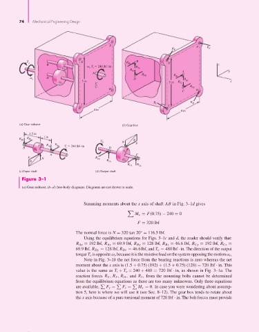
Figure 3–1
(a) Gear reducer; (b–d) free-body diagrams. Diagrams are not drawn to scale.
Summing moments about the x axis of shaft AB in Fig. 3–1d gives
M x = F(0.75) − 240 = 0
F = 320 lbf
The normal force is N = 320 tan 20° = 116.5 lbf.
Using the equilibrium equations for Figs. 3–1c and d, the reader should verify that:
R Ay = 192 lbf, R Az = 69.9 lbf, R By = 128 lbf, R Bz = 46.6 lbf, R Cy = 192 lbf, R Cz =
69.9 lbf, R Dy = 128 lbf, R Dz = 46.6 lbf, and T o = 480 lbf · in. The direction of the output
torque T o is opposite ω o because it is the resistive load on the system opposing the motionω o.
Note in Fig. 3–1b the net force from the bearing reactions is zero whereas the net
moment about the x axis is (1.5 + 0.75) (192) + (1.5 + 0.75) (128) = 720 lbf · in. This
value is the same as T i + T o = 240 + 480 = 720 lbf · in, as shown in Fig. 3–1a. The
reaction forces R E , R F , R H , and R I , from the mounting bolts cannot be determined
from the equilibrium equations as there are too many unknowns. Only three equations
are available, F y = F z = M x = 0. In case you were wondering about assump-
tion 5, here is where we will use it (see Sec. 8–12). The gear box tends to rotate about
the x axis because of a pure torsional moment of 720 lbf · in. The bolt forces must provide