
Page 103 - Shigley's Mechanical Engineering Design
P. 103
bud29281_ch03_071-146.qxd 11/26/09 5:56PM Page 78 ntt G4 Mac OS 9.2:Desktop Folder:MHDQ196/Budynas:
78 Mechanical Engineering Design
should give V = 0 at x slightly larger than 20 in. Thus
R 1 − 200 − 100 + R 2 = 0 (4)
Since the bending moment should also be zero in the same region, we have, from Eq. (3),
R 1 (20) − 200(20 − 4) − 100(20 − 10) = 0 (5)
Equations (4) and (5) yield the reactions R 1 210 lbf and R 2 90 lbf.
The reader should verify that substitution of the values of R 1 and R 2 into Eqs. (2)
and (3) yield Figs. 3–5b and c.
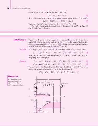
EXAMPLE 3–3 Figure 3–6a shows the loading diagram for a beam cantilevered at A with a uniform
load of 20 lbf/in acting on the portion 3in ≤ x ≤ 7in, and a concentrated counter-
clockwise moment of 240 lbf · in at x = 10 in. Derive the shear-force and bending-
moment relations, and the support reactions M 1 and R 1 .
Solution Following the procedure of Example 3–2, we find the load intensity function to be
−2 −1 0 0 −2
q =−M 1 x + R 1 x − 20 x − 3 + 20 x − 7 − 240 x − 10 (1)
0
Note that the 20 x − 7 term was necessary to “turn off” the uniform load at C.
Integrating successively gives
Answers V =−M 1 x −1 + R 1 x − 20 x − 3 + 20 x − 7 − 240 x − 10 −1 (2)
1
0
1
0 1 2 2 0
M =−M 1 x + R 1 x − 10 x − 3 + 10 x − 7 − 240 x − 10 (3)
The reactions are found by making x slightly larger than 10 in, where both V and M are
−1
zero in this region. Noting that 10 = 0, Eq. (2) will then give
−M 1 (0) + R 1 (1) − 20(10 − 3) + 20(10 − 7) − 240(0) = 0
Figure 3–6 y
(a) Loading diagram for a q 10 in
beam cantilevered at A. 7 in
(b) Shear-force diagram. 3 in 20 lbf/in
240 lbf in
(c) Bending-moment diagram. D
x
A B C
M
(a) 1 R 1
V (lbf)
Step
80 Ramp
(b) O x
M (lbf in)
Parabolic Step
240
80
O x
Ramp
–160 Slope = 80 lbf in/in
(c)