Page 120 - Shigley's Mechanical Engineering Design
P. 120

bud29281_ch03_071-146.qxd  11/25/09  4:55PM  Page 95 ntt 203:MHDQ196:bud29281:0073529281:bud29281_pagefiles:


                                                                                               Load and Stress Analysis  95
                                       w(x)
                      y                                                My                          x       My     dMy
                                                                 x
                                                                     I
                                                                                                           I
                                                                                                       I
                                                                                     c
                                                                                 y 1            x
                                    V         M   dM
                                 M                          x
                                           V   dV
                                                                                   dx
                             x         dx
                                                                                   (b)
                                       (a)
                                                                         A
                                                                             c
                                                  y                      F     dM y
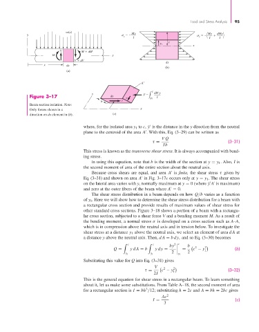
                       Figure 3–17                         dx                y 1  I
                                                       b
                       Beam section isolation. Note:
                                                                        x
                       Only forces shown in x
                       direction on dx element in (b).      (c)


                                               where, for the isolated area y 1 to c,  ¯y is the distance in the y direction from the neutral

                                               plane to the centroid of the area A . With this, Eq. (3–29) can be written as
                                                                                  VQ
                                                                              τ =                              (3–31)
                                                                                  Ib
                                               This stress is known as the transverse shear stress. It is always accompanied with bend-
                                               ing stress.
                                                  In using this equation, note that b is the width of the section at y = y 1 . Also, I is
                                               the second moment of area of the entire section about the neutral axis.
                                                  Because cross shears are equal, and area  A is  finite, the shear stress  τ given by

                                               Eq. (3–31) and shown on area A in Fig. 3–17c occurs only at y = y 1 . The shear stress


                                               on the lateral area varies with y, normally maximum at y = 0 (where ¯y A is maximum)

                                               and zero at the outer fibers of the beam where A   0.
                                                  The shear stress distribution in a beam depends on how Q/b varies as a function
                                               of y 1 . Here we will show how to determine the shear stress distribution for a beam with
                                               a rectangular cross section and provide results of maximum values of shear stress for
                                               other standard cross sections. Figure 3–18 shows a portion of a beam with a rectangu-
                                               lar cross section, subjected to a shear force V and a bending moment M. As a result of
                                               the bending moment, a normal stress σ is developed on a cross section such as A–A,
                                               which is in compression above the neutral axis and in tension below. To investigate the
                                               shear stress at a distance y 1 above the neutral axis, we select an element of area dA at
                                               a distance y above the neutral axis. Then, dA = bdy, and so Eq. (3–30) becomes


                                                                   c           c       2 c
                                                                                     by      b    2  2
                                                            Q =     yd A = b   ydy =       =    c − y 1           (b)
                                                                                      2      2
                                                                  y 1        y 1         y 1
                                               Substituting this value for Q into Eq. (3–31) gives
                                                                              V    2   2
                                                                          τ =     c − y 1                      (3–32)
                                                                              2I
                                               This is the general equation for shear stress in a rectangular beam. To learn something
                                               about it, let us make some substitutions. From Table A–18, the second moment of area
                                                                           3
                                               for a rectangular section is I = bh /12; substituting h = 2c and A = bh = 2bc gives
                                                                                  Ac 2
                                                                              I =                                 (c)
                                                                                   3
   115   116   117   118   119   120   121   122   123   124   125