
Page 124 - Shigley's Mechanical Engineering Design
P. 124
bud29281_ch03_071-146.qxd 11/25/09 5:15PM Page 99 ntt G4 Mac OS 9.2:Desktop Folder:
Load and Stress Analysis 99
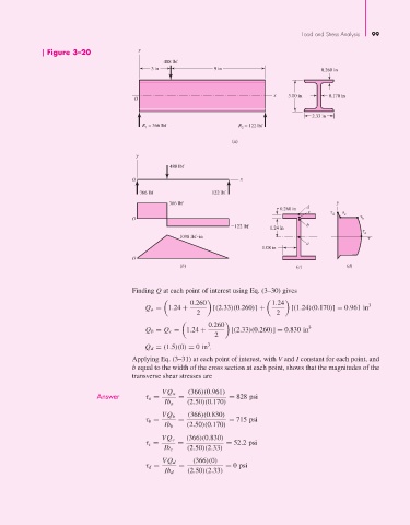
Figure 3–20 y
488 lbf
3 in 9 in 0.260 in
x 3.00 in 0.170 in
O
2.33 in
R = 366 lbf R = 122 lbf
1
2
(a)
y
488 lbf
O x
366 lbf 122 lbf
366 lbf y
0.260 in d
c
d c
O b
2122 lbf 1.24 in b
a
1098 lbf in
a
1.08 in
O
(b) (c) (d)
Finding Q at each point of interest using Eq. (3–30) gives
0.260 1.24 3
Q a = 1.24 + [(2.33)(0.260)] + [(1.24)(0.170)] = 0.961 in
2 2
0.260 3
Q b = Q c = 1.24 + [(2.33)(0.260)] = 0.830 in
2
Q d = (1.5)(0) = 0in 3 p
Applying Eq. (3–31) at each point of interest, with V and I constant for each point, and
b equal to the width of the cross section at each point, shows that the magnitudes of the
transverse shear stresses are
Answer τ a = VQ a = (366)(0.961) = 828 psi
Ib a (2.50)(0.170)
VQ b (366)(0.830)
τ b = = = 715 psi
Ib b (2.50)(0.170)
VQ c (366)(0.830)
τ c = = = 52.2 psi
Ib c (2.50)(2.33)
VQ d (366)(0)
τ d = = = 0 psi
Ib d (2.50)(2.33)