
Page 123 - Shigley's Mechanical Engineering Design
P. 123
bud29281_ch03_071-146.qxd 11/24/09 3:01PM Page 98 ntt 203:MHDQ196:bud29281:0073529281:bud29281_pagefiles:
98 Mechanical Engineering Design
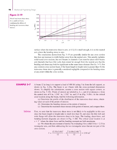
Figure 3–19 1400
1200
Plot of maximum shear stress
for a cantilever beam, y⁄c = 1
1000
combining the effects of
max (MPa)
bending and transverse shear 800
stresses. 600 y⁄c = 2 3
400
y⁄c = 1 3
200
y⁄c = 0
0
0 0.5 1 1.5 2 2.5 3 3.5 4
L/h
surface where the transverse shear is zero, or if L/h is small enough, it is on the neutral
axis where the bending stress is zero.
The conclusions drawn from Fig. 3–19 are generally similar for any cross section
that does not increase in width farther away from the neutral axis. This notably includes
solid round cross sections, but not I beams or channels. Care must be taken with I beams
and channels that have thin webs that extend far enough from the neutral axis that the
bending and shear may both be significant on the same stress element (See Ex. 3–7). For
any common cross section beam, if the beam length to height ratio is greater than 10, the
transverse shear stress is generally considered negligible compared to the bending stress
at any point within the cross section.
EXAMPLE 3–7 A beam 12 in long is to support a load of 488 lbf acting 3 in from the left support, as
shown in Fig. 3–20a. The beam is an I beam with the cross-sectional dimensions
shown. To simplify the calculations, assume a cross section with square corners, as
shown in Fig. 3–20c. Points of interest are labeled (a, b, c, and d) at distances y from
the neutral axis of 0 in, 1.240 in, 1.240 in, and 1.5 in (Fig. 3–20c). At the critical
axial location along the beam, find the following information.
(a) Determine the profile of the distribution of the transverse shear stress, obtain-
ing values at each of the points of interest.
(b) Determine the bending stresses at the points of interest.
(c) Determine the maximum shear stresses at the points of interest, and compare them.
Solution First, we note that the transverse shear stress is not likely to be negligible in this case
since the beam length to height ratio is much less than 10, and since the thin web and
wide flange will allow the transverse shear to be large. The loading, shear-force, and
bending-moment diagrams are shown in Fig. 3–20b. The critical axial location is at
x 3 where the shear force and the bending moment are both maximum.
(a) We obtain the area moment of inertia I by evaluating I for a solid 3.0-in 2.33-in
rectangular area, and then subtracting the two rectangular areas that are not part of the
cross section.
(2.33)(3.00) 3 (1.08)(2.48) 3 4
I = − 2 = 2.50 in
12 12