
Page 129 - Shigley's Mechanical Engineering Design
P. 129
bud29281_ch03_071-146.qxd 11/24/09 3:02PM Page 104 ntt 203:MHDQ196:bud29281:0073529281:bud29281_pagefiles:
104 Mechanical Engineering Design
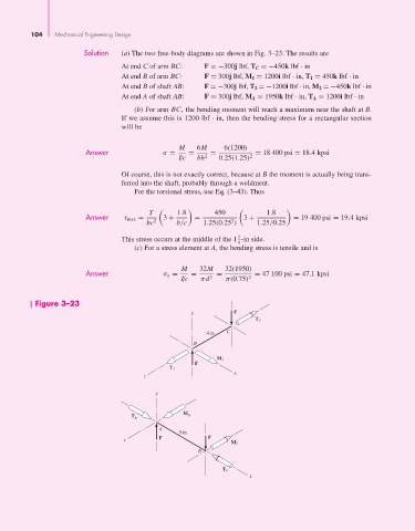
Solution (a) The two free-body diagrams are shown in Fig. 3–23. The results are
At end C of arm BC: F =−300j lbf, T C =−450k lbf · in
At end B of arm BC: F = 300j lbf, M 1 = 1200i lbf · in, T 1 = 450k lbf · in
At end B of shaft AB: F =−300j lbf, T 2 =−1200i lbf · in, M 2 =−450k lbf · in
At end A of shaft AB: F = 300j lbf, M A = 1950k lbf · in, T A = 1200i lbf · in
(b) For arm BC, the bending moment will reach a maximum near the shaft at B.
If we assume this is 1200 lbf · in, then the bending stress for a rectangular section
will be
M 6M 6(1200)
Answer σ = = = = 18 400 psi = 18.4 kpsi
I/c bh 2 0.25(1.25) 2
Of course, this is not exactly correct, because at B the moment is actually being trans-
ferred into the shaft, probably through a weldment.
For the torsional stress, use Eq. (3–43). Thus
T 1.8 450 1.8
Answer τ max = 3 + = 3 + = 19 400 psi = 19.4 kpsi
2
bc 2 b/c 1.25(0.25 ) 1.25/0.25
1
This stress occurs at the middle of the 1 -in side.
4
(c) For a stress element at A, the bending stress is tensile and is
M 32M 32(1950)
Answer σ x = = = = 47 100 psi = 47.1 kpsi
I/c πd 3 π(0.75) 3
Figure 3–23
y F
T C
4 in C
B
M 1
F
T 1
x
z
y
M
T A A
A
5 in
F F
z
M 2
B
T 2
x