
Page 136 - Shigley's Mechanical Engineering Design
P. 136
bud29281_ch03_071-146.qxd 11/25/09 5:15PM Page 111 ntt G4 Mac OS 9.2:Desktop Folder:
Load and Stress Analysis 111
A theoretical, or geometric, stress-concentration factor K t or K ts is used to relate
the actual maximum stress at the discontinuity to the nominal stress. The factors are
defined by the equations
σ max τ max
K t = K ts = (3–48)
σ 0 τ 0
where K t is used for normal stresses and K ts for shear stresses. The nominal stress σ 0 or
τ 0 is the stress calculated by using the elementary stress equations and the net area, or
net cross section. Sometimes the gross cross section is used instead, and so it is always
wise to double check the source of K t or K ts before calculating the maximum stress.
The stress-concentration factor depends for its value only on the geometry of the
part. That is, the particular material used has no effect on the value of K t. This is why
it is called a theoretical stress-concentration factor.
The analysis of geometric shapes to determine stress-concentration factors is a
difficult problem, and not many solutions can be found. Most stress-concentration
9
factors are found by using experimental techniques. Though the finite-element
method has been used, the fact that the elements are indeed finite prevents finding the
true maximum stress. Experimental approaches generally used include photoelasticity,
grid methods, brittle-coating methods, and electrical strain-gauge methods. Of course,
the grid and strain-gauge methods both suffer from the same drawback as the finite-
element method.
Stress-concentration factors for a variety of geometries may be found in
Tables A–15 and A–16.
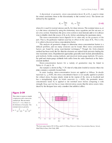
An example is shown in Fig. 3–29, that of a thin plate loaded in tension where the
plate contains a centrally located hole.
In static loading, stress-concentration factors are applied as follows. In ductile
materials ( f ≥ 0.05), the stress-concentration factor is not usually applied to predict
the critical stress, because plastic strain in the region of the stress is localized and
has a strengthening effect. In brittle materials ( f < 0.05), the geometric stress-
concentration factor K t is applied to the nominal stress before comparing it with
strength. Gray cast iron has so many inherent stress raisers that the stress raisers intro-
duced by the designer have only a modest (but additive) effect.
Figure 3–29 3.0
d
Thin plate in tension or simple
2.8
compression with a transverse w
central hole. The net tensile
force is F = σwt, where t is 2.6
the thickness of the plate. The K
t
nominal stress is given by
2.4
F w
σ 0 = = σ
(w − d)t (w − d)
2.2
2.0
0 0.1 0.2 0.3 0.4 0.5 0.6 0.7 0.8
d/w
9 The best source book is W. D. Pilkey and D. F. Pilkey, Peterson’s Stress Concentration Factors, 3rd ed.,
John Wiley & Sons, New York, 2008.