Page 138 - Shigley's Mechanical Engineering Design
P. 138

bud29281_ch03_071-146.qxd  11/25/09  4:55PM  Page 113 ntt 203:MHDQ196:bud29281:0073529281:bud29281_pagefiles:


                                                                                             Load and Stress Analysis  113
                                     Answer       σ max = K t σ 0 = 2.5(156) = 390 MPa

                                               Though the stress concentration is higher with the 4-mm hole, in this case the increased
                                               nominal stress with the 8-mm hole has more effect on the maximum stress.
                                                  For the fillet,

                                                                         F    10 000
                                                                     σ 0 =  =        = 147 MPa
                                                                          A    (34)2
                                               From Table A–15–5, D/d = 40/34 = 1.18, and r/d = 1/34 = 0.026. Then K t = 2.5.

                                     Answer       σ max = K t σ 0 = 2.5(147) = 368 MPa

                                     Answer    The crack will most likely occur with the 8-mm hole, next likely would be the 4-mm
                                               hole, and least likely at the fillet.


                                     3–14      Stresses in Pressurized Cylinders
                                               Cylindrical pressure vessels, hydraulic cylinders, gun barrels, and pipes carrying fluids
                                               at high pressures develop both radial and tangential stresses with values that depend
                                               upon the radius of the element under consideration. In determining the radial stress σ r
                                               and the tangential stress  σ t , we make use of the assumption that the longitudinal
                                               elongation is constant around the circumference of the cylinder. In other words, a right
                                               section of the cylinder remains plane after stressing.
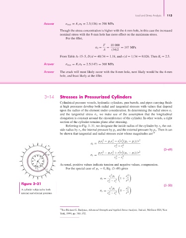
                                                  Referring to Fig. 3–31, we designate the inside radius of the cylinder by r i, the out-
                                               side radius by r o, the internal pressure by p i, and the external pressure by p o. Then it can
                                               be shown that tangential and radial stresses exist whose magnitudes are 10

                                                                                    2 2
                                                                         2
                                                                               2
                                                                       p i r − p o r − r r (p o − p i )/r 2
                                                                         i
                                                                                   i o
                                                                               o
                                                                  σ t =
                                                                                  2
                                       p                                         r − r 2
                                        o
                                                                                 o    i
                                                                                                               (3–49)
                                                                         2
                                                                                    2 2
                                                                               2
                                                                       p i r − p o r + r r (p o − p i )/r 2
                                       dr                         σ r =  i     o   i o
                                                                                  2
                                                                                 r − r 2
                                  r                                              o    i
                               p i
                                               As usual, positive values indicate tension and negative values, compression.
                                                  For the special case of p o = 0, Eq. (3–49) gives
                                 r i  r
                                       o
                                                                              2          2
                                                                             r p i      r o
                                                                              i
                                                                        σ t =    2  1 +
                                                                             2
                                                                            r − r i     r 2
                                                                             o
                       Figure 3–31                                                                             (3–50)
                                                                              2         r 2
                       A cylinder subjected to both                          r p i       o
                                                                              i
                                                                        σ r =    2  1 −
                                                                             2
                       internal and external pressure.                      r − r       r 2
                                                                             o   i
                                               10 See Richard G. Budynas, Advanced Strength and Applied Stress Analysis, 2nd ed., McGraw-Hill, New
                                               York, 1999, pp. 348–352.
   133   134   135   136   137   138   139   140   141   142   143