
Page 143 - Shigley's Mechanical Engineering Design
P. 143
bud29281_ch03_071-146.qxd 11/24/09 3:02PM Page 118 ntt 203:MHDQ196:bud29281:0073529281:bud29281_pagefiles:
118 Mechanical Engineering Design
3–18 Curved Beams in Bending 13
The distribution of stress in a curved flexural member is determined by using the
following assumptions:
• The cross section has an axis of symmetry in the plane of bending.
• Plane cross sections remain plane after bending.
• The modulus of elasticity is the same in tension as in compression.
We shall find that the neutral axis and the centroidal axis of a curved beam,
unlike the axes of a straight beam, are not coincident and also that the stress does
not vary linearly from the neutral axis. The notation shown in Fig. 3–34 is defined
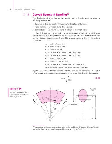
as follows:
r o = radius of outer fiber
r i = radius of inner fiber
h = depth of section
c o = distance from neutral axis to outer fiber
c i = distance from neutral axis to inner fiber
r n = radius of neutral axis
r c = radius of centroidal axis
e = distance from centroidal axis to neutral axis
M = bending moment; positive M decreases curvature
Figure 3–34 shows that the neutral and centroidal axes are not coincident. The location
of the neutral axis with respect to the center of curvature O is given by the equation
A
(3–63)
r n =
dA
r
Figure 3–34 a b' Centroidal
b
axis
Note that y is positive in the
direction toward the center of c o
curvature, point O. h e
y y
c i M
d c
M
c' Neutral axis
r
o
r
r n c
r i d r
r n
O O
13 For a complete development of the relations in this section, see Richard G. Budynas, Advanced Strength
and Applied Stress Analysis, 2nd ed., Mcgraw-Hill, New York, 1999, pp. 309–317.