
Page 144 - Shigley's Mechanical Engineering Design
P. 144
bud29281_ch03_071-146.qxd 12/31/09 3:12 PM Page 119 epg Disk1:Desktop Folder:TEMPWORK:Don't-Delete Jobs:MHDQ196/Budynas:
Load and Stress Analysis 119
Furthermore, it can be shown that the stress distribution is given by
My
σ = (3–64)
Ae(r n − y)
where M is positive in the direction shown in Fig. 3–34. The stress distribution given
by Eq. (3–64) is hyperbolic and not linear as is the case for straight beams. The critical
stresses occur at the inner and outer surfaces where y = c i and y = c o, respectively,
and are
Mc i Mc o
σ i = σ o =− (3–65)
Aer i Aer o
These equations are valid for pure bending. In the usual and more general case, such as
a crane hook, the U frame of a press, or the frame of a C clamp, the bending moment is
due to a force acting at a distance from the cross section under consideration. Thus, the
cross section transmits a bending moment and an axial force. The axial force is located
at the centroidal axis of the section and the bending moment is then computed at this
location. The tensile or compressive stress due to the axial force, from Eq. (3–22), is then
added to the bending stresses given by Eqs. (3–64) and (3–65) to obtain the resultant
stresses acting on the section.
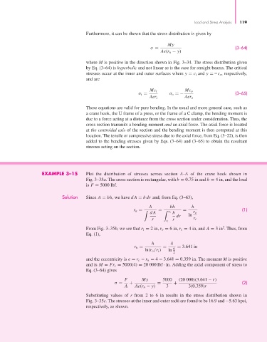
EXAMPLE 3–15 Plot the distribution of stresses across section A–A of the crane hook shown in
Fig. 3–35a. The cross section is rectangular, with b = 0.75 in and h = 4 in, and the load
is F = 5000 lbf.
Solution Since A = bh, we have dA = bdr and, from Eq. (3–63),
A bh h
= (1)
dA r o b r o
r n = =
dr ln
r r r i
r i
2
From Fig. 3–35b, we see that r i = 2 in, r o = 6 in, r c = 4 in, and A = 3 in . Thus, from
Eq. (1),
h 4
r n = = = 3.641 in
ln(r o /r i ) ln 6
2
and the eccentricity is e = r c − r n = 4 − 3.641 = 0.359 in. The moment M is positive
and is M = Fr c = 5000(4) = 20 000 lbf · in. Adding the axial component of stress to
Eq. (3–64) gives
F My 5000 (20 000)(3.641 − r)
σ = + = + (2)
A Ae(r n − y) 3 3(0.359)r
Substituting values of r from 2 to 6 in results in the stress distribution shown in
Fig. 3–35c. The stresses at the inner and outer radii are found to be 16.9 and −5.63 kpsi,
respectively, as shown.