
Page 145 - Shigley's Mechanical Engineering Design
P. 145
bud29281_ch03_071-146.qxd 12/31/09 3:42 PM Page 120 epg Disk1:Desktop Folder:TEMPWORK:Don't-Delete Jobs:MHDQ196/Budynas:
120 Mechanical Engineering Design
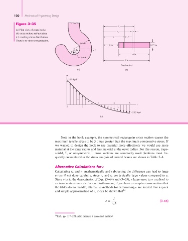
Figure 3–35
r c
(a) Plan view of crane hook;
r e
(b) cross section and notation; n
(c) resulting stress distribution. r y
There is no stress concentration.
6-in R.
2 in 0.75 in
A A
F
4 in
2-in R.
6 in
Section A–A
(a) (b)
16.9 kpsi
+
4 5 6
r
2 3
–
–5.63 kpsi
(c)
Note in the hook example, the symmetrical rectangular cross section causes the
maximum tensile stress to be 3 times greater than the maximum compressive stress. If
we wanted to design the hook to use material more effectively we would use more
material at the inner radius and less material at the outer radius. For this reason, trape-
zoidal, T, or unsymmetric I, cross sections are commonly used. Sections most fre-
quently encountered in the stress analysis of curved beams are shown in Table 3–4.
Alternative Calculations for e
Calculating r n and r c mathematically and subtracting the difference can lead to large
errors if not done carefully, since r n and r c are typically large values compared to e.
Since e is in the denominator of Eqs. (3–64) and (3–65), a large error in e can lead to
an inaccurate stress calculation. Furthermore, if you have a complex cross section that
the tables do not handle, alternative methods for determining e are needed. For a quick
and simple approximation of e, it can be shown that 14
. I
e = (3–66)
r c A
14 Ibid., pp. 317–321. Also presents a numerical method.