Page 142 - Shigley's Mechanical Engineering Design
P. 142

bud29281_ch03_071-146.qxd  11/24/09  3:02PM  Page 117 ntt 203:MHDQ196:bud29281:0073529281:bud29281_pagefiles:


                                                                                             Load and Stress Analysis  117
                                               and, for the outer member

                                                                                     2    2
                                                                                    r + R
                                                                                     o
                                                                                = p                            (3–59)
                                                                                     2
                                                                                    r − R 2
                                                                        (σ t ) o
                                                                             r=R     o
                                               Assumptions
                                               It is assumed that both members have the same length. In the case of a hub that has been
                                               press-fitted onto a shaft, this assumption would not be true, and there would be an increased
                                               pressure at each end of the hub. It is customary to allow for this condition by employing a
                                               stress-concentration factor. The value of this factor depends upon the contact pressure and
                                               the design of the female member, but its theoretical value is seldom greater than 2.
                                     3–17      Temperature Effects
                                               When the temperature of an unrestrained body is uniformly increased, the body expands,
                                               and the normal strain is
                                                                          x =   y =   z = α( T)                (3–60)
                                               where α is the coefficient of thermal expansion and  T is the temperature change, in
                                               degrees. In this action the body experiences a simple volume increase with the compo-
                                               nents of shear strain all zero.
                                                  If a straight bar is restrained at the ends so as to prevent lengthwise expansion and
                                               then is subjected to a uniform increase in temperature, a compressive stress will develop
                                               because of the axial constraint. The stress is
                                                                        σ =− E =−α( T)E                        (3–61)
                                                  In a similar manner, if a uniform flat plate is restrained at the edges and also sub-
                                               jected to a uniform temperature rise, the compressive stress developed is given by the
                                               equation
                                                                                α( T)E
                                                                           σ =−                                (3–62)
                                                                                  1 − ν
                                                  The stresses expressed by Eqs. (3–61) and (3–62) are called  thermal stresses.
                                               They arise because of a temperature change in a clamped or restrained member. Such
                                               stresses, for example, occur during welding, since parts to be welded must be clamped
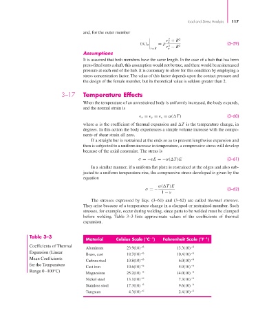
                                               before welding. Table 3–3 lists approximate values of the coefficients of thermal
                                               expansion.


                       Table 3–3
                                                Material      Celsius Scale (°C )  Fahrenheit Scale (°F )
                                                                              1
                                                                                                     −1
                       Coefficients of Thermal                           −6                     −6
                                                Aluminum          23.9(10)               13.3(10)
                       Expansion (Linear                                −6                     −6
                                                Brass, cast       18.7(10)               10.4(10)
                       Mean Coefficients                                 −6                     −6
                                                Carbon steel      10.8(10)                6.0(10)
                       for the Temperature                              −6                     −6
                                                Cast iron         10.6(10)                5.9(10)
                       Range 0–100°C)                                   −6                     −6
                                                Magnesium         25.2(10)               14.0(10)
                                                Nickel steel      13.1(10) −6             7.3(10) −6
                                                Stainless steel   17.3(10) −6             9.6(10) −6
                                                Tungsten           4.3(10) −6             2.4(10) −6
   137   138   139   140   141   142   143   144   145   146   147