
Page 137 - Shigley's Mechanical Engineering Design
P. 137
bud29281_ch03_071-146.qxd 11/25/09 4:55PM Page 112 ntt 203:MHDQ196:bud29281:0073529281:bud29281_pagefiles:
112 Mechanical Engineering Design
Consider a part made of a ductile material and loaded by a gradually applied sta-
tic load such that the stress in an area of a stress concentration goes beyond the yield
strength. The yielding will be restricted to a very small region, and the permanent
deformation as well as the residual stresses after the load is released will be insignifi-
cant and normally can be tolerated. If yielding does occur, the stress distribution
changes and tends toward a more uniform distribution. In the region where yielding
occurs, there is little danger of fracture of a ductile material, but if the possibility of a
brittle fracture exists, the stress concentration must be taken seriously. Brittle fracture
is not just limited to brittle materials. Materials often thought of as being ductile can
fail in a brittle manner under certain conditions, e.g., any single application or combi-
nation of cyclic loading, rapid application of static loads, loading at low temperatures,
and parts containing defects in their material structures (see Sec. 5–12). The effects on
a ductile material of processing, such as hardening, hydrogen embrittlement, and
welding, may also accelerate failure. Thus, care should always be exercised when deal-
ing with stress concentrations.
For dynamic loading, the stress concentration effect is significant for both ductile
and brittle materials and must always be taken into account (see Sec. 6–10).
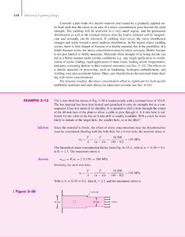
EXAMPLE 3–13 The 2-mm-thick bar shown in Fig. 3–30 is loaded axially with a constant force of 10 kN.
The bar material has been heat treated and quenched to raise its strength, but as a con-
sequence it has lost most of its ductility. It is desired to drill a hole through the center
of the 40-mm face of the plate to allow a cable to pass through it. A 4-mm hole is suf-
ficient for the cable to fit, but an 8-mm drill is readily available. Will a crack be more
likely to initiate at the larger hole, the smaller hole, or at the fillet?
Solution Since the material is brittle, the effect of stress concentrations near the discontinuities
must be considered. Dealing with the hole first, for a 4-mm hole, the nominal stress is
F F 10 000
σ 0 = = = = 139 MPa
A (w − d)t (40 − 4)2
The theoretical stress concentration factor, from Fig. A–15–1, with d/w 4/40 0.1,
is Kt 2.7. The maximum stress is
Answer σ max = K t σ 0 = 2.7(139) = 380 MPa
Similarly, for an 8-mm hole,
F F 10 000
σ 0 = = = = 156 MPa
A (w − d)t (40 − 8)2
With d/w = 8/40 = 0.2, then K 2.5, and the maximum stress is
t
Figure 3–30 1 mm rad
40 mm 34 mm 10 kN