
Page 148 - Shigley's Mechanical Engineering Design
P. 148
bud29281_ch03_071-146.qxd 11/24/09 3:02PM Page 123 ntt 203:MHDQ196:bud29281:0073529281:bud29281_pagefiles:
Load and Stress Analysis 123
Spherical Contact
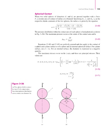
When two solid spheres of diameters d 1 and d 2 are pressed together with a force
F, a circular area of contact of radius a is obtained. Specifying E 1 , ν 1 and E 2 , ν 2 as the
respective elastic constants of the two spheres, the radius a is given by the equation
2 2
3F 1 − ν E 1 + 1 − ν (3–68)
3 1 2 E 2
a =
8 1/d 1 + 1/d 2
The pressure distribution within the contact area of each sphere is hemispherical, as shown
in Fig. 3–36b. The maximum pressure occurs at the center of the contact area and is
3F
p max = 2 (3–69)
2πa
Equations (3–68) and (3–69) are perfectly general and also apply to the contact of
a sphere and a plane surface or of a sphere and an internal spherical surface. For a plane
surface, use d =∞. For an internal surface, the diameter is expressed as a negative
quantity.
The maximum stresses occur on the z axis, and these are principal stresses. Their
values are
⎡ ⎤
1 1
⎢ z −1 ⎥
σ 1 = σ 2 = σ x = σ y =−p max ⎢ 1 − tan (1 + ν) − 2 ⎥
a
⎣ |z/a| z ⎦
2 1 +
a 2
(3–70)
−p max
σ 3 = σ z = 2
z (3–71)
1 +
a 2
Figure 3–36 F F
(a) Two spheres held in contact
x
by force F; (b) contact stress
has a hemispherical distribution
across contact zone diameter 2a. d 1
y y
2a
d 2
F F
z z
(a) (b)