
Page 152 - Shigley's Mechanical Engineering Design
P. 152
bud29281_ch03_071-146.qxd 11/25/09 4:55PM Page 127 ntt 203:MHDQ196:bud29281:0073529281:bud29281_pagefiles:
Load and Stress Analysis 127
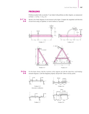
PROBLEMS
Problems marked with an asterisk (*) are linked with problems in other chapters, as summarized
in Table 1–1 of Sec. 1–16, p. 24.
3–1* to Sketch a free-body diagram of each element in the figure. Compute the magnitude and direction
3–4 of each force using an algebraic or vector method, as specified.
B
C
100 lbf
y 100 lbf
12 in
10 in
O C
A x A
O B
6 in 12 in 10 in 10 in 10 in
Problem 3–1* Problem 3–2
F = 400 N y
y
B 30° C
F = 0.8 kN
4
3
0.9 m 2 3
2 B D
60° 1.9 m 60° E
60° x
O A A O 1 5
x
1
9 m
Problem 3–3 Problem 3–4
3–5 to For the beam shown, find the reactions at the supports and plot the shear-force and bending-
3–8 moment diagrams. Label the diagrams properly and provide values at all key points.
y
9 kN 5 kN y 500 lbf 40 lbf/in
300 900 300
O x
A B C O A B C
x
R 1 R 2 8 in 6 in 6 in
Problem 3–5 Problem 3–6
Dimensions in millimeters
Hinge
y
400 lbf 40 lbf/in
y
2 kN 4 kN
O x
1.2 m 1 m 1 m AB C D
O x
A B C R 1 R 2 R 3
R 1 R 2 4 in 4 in 2 in 10 in
Problem 3–7 Problem 3–8