
Page 155 - Shigley's Mechanical Engineering Design
P. 155
bud29281_ch03_071-146.qxd 11/26/2009 10:07 pm Page 130 pinnacle s-171:Desktop Folder:Temp Work:Don't Delete (Jobs):MHDQ196/Budynas:
130 Mechanical Engineering Design
(b) Subscript every parameter with m (for model) and divide into the above equation. Introduce
a scale factor, s = a m /a = b m /b = c m /c etc. Since the Roman method was to not “lean on”
the material any more than the proven design, set σ m /σ = 1. Express F m in terms of the scale
factors and F, and comment on what you have learned.
F c
a
Problem 3–31 R 2
h
b
l
R 1
3–32 Using our experience with concentrated loading on a simple beam, Prob. 3–31, consider a uni-
formly loaded simple beam (Table A–9–7).
(a) Show that the stress-to-load equation for a rectangular-cross-section beam is given by
4 σbh 2
W =
3 l
where W = wl.
(b) Subscript every parameter with m (for model) and divide the model equation into the proto-
type equation. Introduce the scale factor s as in Prob. 3–31, setting σ m /σ = 1. Express W m
and w m in terms of the scale factor, and comment on what you have learned.
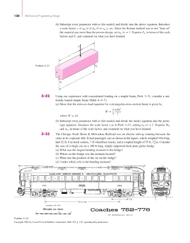
3–33 The Chicago North Shore & Milwaukee Railroad was an electric railway running between the
cities in its corporate title. It had passenger cars as shown in the figure, which weighed 104.4 kip,
1
had 32-ft, 8-in truck centers, 7-ft-wheelbase trucks, and a coupled length of 55 ft, 3 in. Consider
4
the case of a single car on a 100-ft-long, simply supported deck plate girder bridge.
(a) What was the largest bending moment in the bridge?
(b) Where on the bridge was the moment located?
(c) What was the position of the car on the bridge?
(d) Under which axle is the bending moment?
7 ft
32 ft, 8 in
Problem 3–33
Copyright 1963 by Central Electric Railfans Association, Bull. 107, p. 145, reproduced by permission.