
Page 156 - Shigley's Mechanical Engineering Design
P. 156
bud29281_ch03_071-146.qxd 11/25/09 4:55PM Page 131 ntt 203:MHDQ196:bud29281:0073529281:bud29281_pagefiles:
Load and Stress Analysis 131
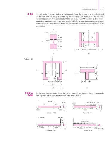
3–34 For each section illustrated, find the second moment of area, the location of the neutral axis, and
the distances from the neutral axis to the top and bottom surfaces. Consider that the section is
transmitting a positive bending moment about the z axis, M z, where M z = 10 kip · in if the dimen-
sions of the section are given in ips units, or M z = 1.13 kN . m if the dimensions are in SI units.
Determine the resulting stresses at the top and bottom surfaces and at every abrupt change in the
cross section.
y
y
40 mm
D
D
25 mm 1 in 3 in
8
z C
6 mm C
z 25 mm
B 1 in B
25 mm 2 A
3 in 1 in 3 in
3
A 8 4 8
(a) (b)
y
Problem 3–34
D
C y 7 in
8
4 in
C
z 75 100
12.5 12.5 z B
1
2 in
2
B
12.5
A
25 A
50 7 in
8
100
(c) Dimensions in mm (d)
3–35 to For the beam illustrated in the figure, find the locations and magnitudes of the maximum tensile
3–38 bending stress due to M and the maximum shear stress due to V.
y
y
4500 N
20 mm w = 100 lbf/in 1 in
300 mm 150 mm
x x
O
A B O 8 in A 8 in B
40 mm 2 in
Problem 3–35 Problem 3–36
y 3000 lbf 1000 lbf y
3 in
4 w = 6 kN/mm
x
x
O 5 in A 15 in B 5 in C O 100 mm A 200 mm B
2 in 50 mm dia
Problem 3–37 Problem 3–38