Page 157 - Shigley's Mechanical Engineering Design
P. 157

bud29281_ch03_071-146.qxd  11/30/2009  5:34 pm  Page 132 pinnacle s-171:Desktop Folder:Temp Work:Don't Delete (Jobs):MHDQ196/Budynas:


                 132   Mechanical Engineering Design
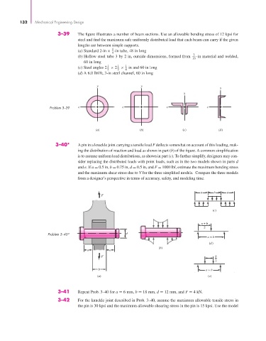
                                 3–39     The figure illustrates a number of beam sections. Use an allowable bending stress of 12 kpsi for
                                          steel and find the maximum safe uniformly distributed load that each beam can carry if the given
                                          lengths are between simple supports.
                                                         1
                                          (a) Standard 2-in × -in tube, 48 in long
                                                         4
                                          (b) Hollow steel tube 3 by 2 in, outside dimensions, formed from   3  -in material and welded,
                                                                                            16
                                             60 in long
                                                       1   1   1
                                          (c) Steel angles 2 × 2 ×  in and 60 in long
                                                       2   2   4
                                          (d) A 6.0 lbf/ft, 3-in steel channel, 60 in long
                                                  y                  y
                                                                                                        y
                                                                                        y


                              Problem 3–39  z                z                  z                 z


                                                  (a)                (b)               (c)             (d)

                                3–40*     A pin in a knuckle joint carrying a tensile load F deflects somewhat on account of this loading, mak-
                                          ing the distribution of reaction and load as shown in part (b) of the figure. A common simplification
                                          is to assume uniform load distributions, as shown in part (c). To further simplify, designers may con-
                                          sider replacing the distributed loads with point loads, such as in the two models shown in parts d
                                          and e. If a = 0.5 in, b = 0.75 in, d = 0.5 in, and F = 1000 lbf, estimate the maximum bending stress
                                          and the maximum shear stress due to V for the three simplified models.  Compare the three models
                                          from a designer’s perspective in terms of accuracy, safety, and modeling time.


                                                                                               a     b     a
                                                    F

                                                                                                     (c)


                                                                                                a + b b
                                                                                                 2
                             Problem 3–40*                     d
                                                                                                  a + b
                                                                                                   (d)
                                                                             (b)
                                              a         a
                                                    F                                                 b
                                                                                                      2
                                                   b                                              a + b
                                                  (a)                                              (e)


                                 3–41     Repeat Prob. 3–40 for a = 6 mm, b = 18 mm, d = 12 mm, and F = 4 kN.
                                 3–42     For the knuckle joint described in Prob. 3–40, assume the maximum allowable tensile stress in
                                          the pin is 30 kpsi and the maximum allowable shearing stress in the pin is 15 kpsi. Use the model
   152   153   154   155   156   157   158   159   160   161   162