Page 162 - Shigley's Mechanical Engineering Design
P. 162

bud29281_ch03_071-146.qxd  11/25/09  4:55PM  Page 137 ntt 203:MHDQ196:bud29281:0073529281:bud29281_pagefiles:


                                                                                             Load and Stress Analysis  137


                                                                                  y
                                                                                d A         d B        d A  d C
                                   Problem 3–65
                                                                                                                    x
                                                                                  A           B          A  C
                                                        (a)                                    (b)

                                      3–66     The conveyer drive roll in the figure for Prob. 3–65 is 5 in in diameter and is driven at 8 rev/min
                                               by a geared-motor source rated at 1 hp. Find a suitable shaft diameter d C based on an allowable
                                               torsional stress of 15 kpsi.
                                      3–67     Consider two shafts in torsion, each of the same material, length, and cross-sectional area. One
                                               shaft has a solid square cross section and the other shaft has a solid circular section.
                                               (a) Which shaft has the greater maximum shear stress and by what percentage?
                                               (b) Which shaft has the greater angular twist θ and by what percentage?
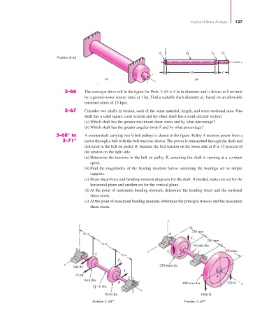
                                  3–68* to     A countershaft carrying two V-belt pulleys is shown in the figure. Pulley A receives power from a
                                     3–71*     motor through a belt with the belt tensions shown. The power is transmitted through the shaft and
                                               delivered to the belt on pulley B. Assume the belt tension on the loose side at B is 15 percent of
                                               the tension on the tight side.
                                               (a) Determine the tensions in the belt on pulley B, assuming the shaft is running at a constant
                                                 speed.
                                               (b) Find the magnitudes of the bearing reaction forces, assuming the bearings act as simple
                                                 supports.
                                               (c) Draw shear-force and bending-moment diagrams for the shaft. If needed, make one set for the
                                                 horizontal plane and another set for the vertical plane.
                                               (d) At the point of maximum bending moment, determine the bending stress and the torsional
                                                 shear stress.
                                               (e) At the point of maximum bending moment, determine the principal stresses and the maximum
                                                 shear stress.


                                                                                   y
                                            y
                                                                                              230 mm
                                              10 in                                 O
                                                                                              T 2
                                                                                                     280 mm
                                                      18 in                                    30-mm dia.
                                           O                               z       T                         300 mm
                                                   A                                1    B       C
                                                               12 in
                                                             T
                                                              2
                                      z                                         250-mm dia.
                                          500 lbf
                                                                T
                                                                 1
                                           75 lbf                 C                                      A
                                               8-in dia.
                                                              B                           400-mm dia.         270 N  x
                                                   1
                                                  1 -in dia.
                                                   4
                                                                       x
                                                       10-in dia.                                 1800 N
                                                  Problem 3–68*                            Problem 3–69*
   157   158   159   160   161   162   163   164   165   166   167