
Page 163 - Shigley's Mechanical Engineering Design
P. 163
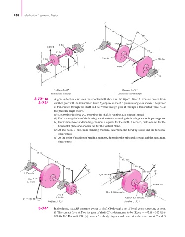
bud29281_ch03_071-146.qxd  11/30/2009  5:35 pm  Page 138 pinnacle s-171:Desktop Folder:Temp Work:Don't Delete (Jobs):MHDQ196/Budynas:


                 138   Mechanical Engineering Design
                                                                         y


                                                                              300
                                                                                                 45°
                                                                        O               400
                                                             x
                                             6 dia.                             45 N   300 N
                                     300 lbf                C
                                                                   z                                150
                                  y        50 lbf
                                                        T
                                                 B       2
                                   1 dia.                               250 dia.   A                       300 dia.
                                                       T 1
                                        A            6
                                              8 dia.                             20 dia.  T 2
                                O      z      8                                                  B
                                                                                                         C  x
                                      8
                                                                                          T
                                                                                           1
                                          Problem 3–70*                              Problem 3–71*
                                        Dimensions in inches.                     Dimensions in millimeters.
                              3–72* to    A gear reduction unit uses the countershaft shown in the figure. Gear A receives power from
                                3–73*     another gear with the transmitted force F A  applied at the 20  pressure angle as shown. The power
                                          is transmitted through the shaft and delivered through gear B through a transmitted force F B at
                                          the pressure angle shown.
                                          (a) Determine the force F B , assuming the shaft is running at a constant speed.
                                          (b) Find the magnitudes of the bearing reaction forces, assuming the bearings act as simple supports.
                                          (c) Draw shear-force and bending-moment diagrams for the shaft. If needed, make one set for the
                                            horizontal plane and another set for the vertical plane.
                                          (d) At the point of maximum bending moment, determine the bending stress and the torsional
                                             shear stress.
                                          (e) At the point of maximum bending moment, determine the principal stresses and the maximum
                                             shear stress.
                           y

                                16 in                                              y

                                                                                    400 mm
                          O
                                          14 in
                                                                                                       F
                                                             F B
                                                                                           350 mm       B
                                                  9 in                           O
                     z                                        20°                                300 mm  25°
                       1.25-in dia.
                                                                      F    11 kN
                                                                      A
                          Gear A                C                           20°
                         20-in dia.  A
                                                   B                    z                               50-mm dia.
                                                                                           A
                                                                          Gear A, 600-mm dia.
                                            Gear B         x                                     B        C
                                           8-in dia.                                  Gear B, 300-mm dia.
                          300 lbf
                       F A
                                20°   Problem 3–72*                                   Problem 3–73*            x
                                3–74*     In the figure, shaft AB transmits power to shaft CD through a set of bevel gears contacting at point
                                          E. The contact force at E on the gear of shaft CD is determined to be (F E ) CD = –92.8i – 362.8j +
                                          808.0k lbf. For shaft CD: (a) draw a free-body diagram and determine the reactions at C and D