
Page 168 - Shigley's Mechanical Engineering Design
P. 168
bud29281_ch03_071-146.qxd 11/25/09 5:50PM Page 143 ntt G4 Mac OS 9.2:Desktop Folder:
Load and Stress Analysis 143
3–105 Repeat Prob. 3–104 with the tank being pressurized to 50 psig.
3–106 Find the maximum shear stress in a 5 -in-diameter circular saw blade if it runs idle at 5000 rev/min.
1
2
5
The saw is 14 gauge (0.0747 in) steel and is used on a -in-diameter arbor. The thickness is uni-
8
form. What is the maximum radial component of stress?
3–107 The maximum recommended speed for a 250-mm-diameter abrasive grinding wheel is 2000 rev/min.
Assume that the material is isotropic; use a bore of 20 mm, ν = 0.24, and a mass density of
3
3320 kg/m , and find the maximum tensile stress at this speed.
3–108 An abrasive cutoff wheel has a diameter of 5 in, is 1 in thick, and has a -in bore. It weighs 5 oz
3
16 4
and is designed to run at 12 000 rev/min. If the material is isotropic and ν = 0.20, find the
maximum shear stress at the design speed.
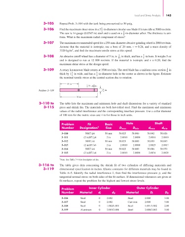
3–109 A rotary lawnmower blade rotates at 3500 rev/min. The steel blade has a uniform cross section in
1
8
1
1
thick by 1 in wide, and has a -in-diameter hole in the center as shown in the figure. Estimate
4 2
the nominal tensile stress at the central section due to rotation.
15 in 1
8 in
1
Problem 3–109 1in
4
30 in
3–110 to The table lists the maximum and minimum hole and shaft dimensions for a variety of standard
3–115 press and shrink fits. The materials are both hot-rolled steel. Find the maximum and minimum
values of the radial interference and the corresponding interface pressure. Use a collar diameter
of 100 mm for the metric sizes and 4 in for those in inch units.
Problem Fit Basic Hole Shaft
Number Designation † Size D max D min d max d min
3–110 50H7 p6 50 mm 50.025 50.000 50.042 50.026
3–111 (2 in)H7 p6 2 in 2.0010 2.0000 2.0016 2.0010
3–112 50H7 s6 50 mm 50.025 50.000 50.059 50.043
3–113 (2 in)H7 s6 2 in 2.0010 2.0000 2.0023 2.0017
3–114 50H7 u6 50 mm 50.025 50.000 50.086 50.070
3–115 (2 in)H7 u6 2 in 2.0010 2.0000 2.0034 2.0028
†
Note: See Table 7–9 for description of fits.
3–116 to The table gives data concerning the shrink fit of two cylinders of differing materials and
3–119 dimensional specification in inches. Elastic constants for different materials may be found in
Table A–5. Identify the radial interference δ, then find the interference pressure p, and the
tangential normal stress on both sides of the fit surface. If dimensional tolerances are given at
fit surfaces, repeat the problem for the highest and lowest stress levels.
Problem Inner Cylinder Outer Cylinder
Number Material d i d 0 Material D i D 0
3–116 Steel 0 2.002 Steel 2.000 3.00
3–117 Steel 0 2.002 Cast iron 2.000 3.00
3–118 Steel 0 1.002/1.003 Steel 1.001/1.002 2.00
3–119 Aluminum 0 2.003/2.006 Steel 2.000/2.002 3.00