
Page 169 - Shigley's Mechanical Engineering Design
P. 169
bud29281_ch03_071-146.qxd 11/25/09 4:55PM Page 144 ntt 203:MHDQ196:bud29281:0073529281:bud29281_pagefiles:
144 Mechanical Engineering Design
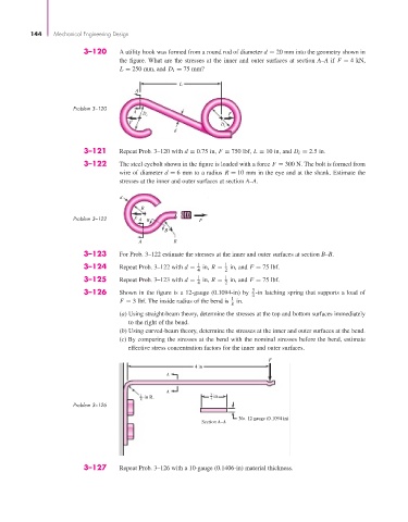
3–120 A utility hook was formed from a round rod of diameter d = 20 mm into the geometry shown in
the figure. What are the stresses at the inner and outer surfaces at section A–A if F = 4 kN,
L = 250 mm, and D i = 75 mm?
L
A
Problem 3–120
A D i F
F D
i
d
3–121 Repeat Prob. 3–120 with d = 0.75 in, F = 750 lbf, L = 10 in, and D i = 2.5 in.
3–122 The steel eyebolt shown in the figure is loaded with a force F = 300 N. The bolt is formed from
wire of diameter d = 6 mm to a radius R = 10 mm in the eye and at the shank. Estimate the
stresses at the inner and outer surfaces at section A–A.
d
R
Problem 3–122 F A B F
B
A R
3–123 For Prob. 3–122 estimate the stresses at the inner and outer surfaces at section B–B.
3–124 Repeat Prob. 3–122 with d = 1 in, R = 1 in, and F = 75 lbf.
4 2
3–125 Repeat Prob. 3–123 with d = 1 in, R = 1 in, and F = 75 lbf.
4 2
3
3–126 Shown in the figure is a 12-gauge (0.1094-in) by -in latching spring that supports a load of
1 4
F = 3 lbf. The inside radius of the bend is in.
8
(a) Using straight-beam theory, determine the stresses at the top and bottom surfaces immediately
to the right of the bend.
(b) Using curved-beam theory, determine the stresses at the inner and outer surfaces at the bend.
(c) By comparing the stresses at the bend with the nominal stresses before the bend, estimate
effective stress concentration factors for the inner and outer surfaces.
F
4 in
A
A
1 -in R. 3 in
8 4
Problem 3–126
No. 12 gauge (0.1094 in)
Section A–A
3–127 Repeat Prob. 3–126 with a 10-gauge (0.1406-in) material thickness.