
Page 173 - Shigley's Mechanical Engineering Design
P. 173
bud29281_ch04_147-211.qxd 12/10/2009 4:05 pm Page 148 pinnacle s-171:Desktop Folder:Temp Work:Don't Delete (Jobs):MHDQ196/Budynas:
148 Mechanical Engineering Design
All real bodies deform under load, either elastically or plastically. A body can be suffi-
ciently insensitive to deformation that a presumption of rigidity does not affect an analy-
sis enough to warrant a nonrigid treatment. If the body deformation later proves to be not
negligible, then declaring rigidity was a poor decision, not a poor assumption. A wire
rope is flexible, but in tension it can be robustly rigid and it distorts enormously under
attempts at compressive loading. The same body can be both rigid and nonrigid.
Deflection analysis enters into design situations in many ways. A snap ring, or retain-
ing ring, must be flexible enough to be bent without permanent deformation and
assembled with other parts, and then it must be rigid enough to hold the assembled parts
together. In a transmission, the gears must be supported by a rigid shaft. If the shaft bends
too much, that is, if it is too flexible, the teeth will not mesh properly, and the result will
be excessive impact, noise, wear, and early failure. In rolling sheet or strip steel to pre-
scribed thicknesses, the rolls must be crowned, that is, curved, so that the finished product
will be of uniform thickness. Thus, to design the rolls it is necessary to know exactly how
much they will bend when a sheet of steel is rolled between them. Sometimes mechanical
elements must be designed to have a particular force-deflection characteristic. The
suspension system of an automobile, for example, must be designed within a very narrow
range to achieve an optimum vibration frequency for all conditions of vehicle loading,
because the human body is comfortable only within a limited range of frequencies.
The size of a load-bearing component is often determined on deflections, rather
than limits on stress.
This chapter considers distortion of single bodies due to geometry (shape) and
loading, then, briefly, the behavior of groups of bodies.
4–1 Spring Rates
Elasticity is that property of a material that enables it to regain its original configuration
after having been deformed. A spring is a mechanical element that exerts a force when
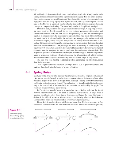
deformed. Figure 4–1a shows a straight beam of length l simply supported at the ends
and loaded by the transverse force F. The deflection y is linearly related to the force, as
long as the elastic limit of the material is not exceeded, as indicated by the graph. This
beam can be described as a linear spring.
In Fig. 4–1b a straight beam is supported on two cylinders such that the length
between supports decreases as the beam is deflected by the force F. A larger force is
required to deflect a short beam than a long one, and hence the more this beam is
deflected, the stiffer it becomes. Also, the force is not linearly related to the deflection,
and hence this beam can be described as a nonlinear stiffening spring.
Figure 4–1c is an edge-view of a dish-shaped round disk. The force necessary to flat-
ten the disk increases at first and then decreases as the disk approaches a flat configuration,
Figure 4–1 l l d
F
(a) A linear spring; F F
(b) a stiffening spring;
(c) a softening spring.
y y y
F F F
y y y
(a) (b) (c)