
Page 176 - Shigley's Mechanical Engineering Design
P. 176
bud29281_ch04_147-211.qxd 11/27/09 2:55PM Page 151 ntt 203:MHDQ196:bud29281:0073529281:bud29281_pagefiles:
Deflection and Stiffness 151
Figure 4–2 y
l = 20 in
w
Loading, w
x
w = 80 lbf/in
wl wl
= R =
(a) R 1 2 2 2
V
V 0 +
Shear, V
x V 0 = +800 lbf
– V l = –800 lbf
V l
(b)
M
+
M M x Moment, M
(c) 0 l M = M = 0
0
l
EI
+ EI l
Slope, EI
x
l/2 = 0
–
EI 0
(d)
EIy
Deflection, EIy
x
l
y 0 = y = 0
–
(e)
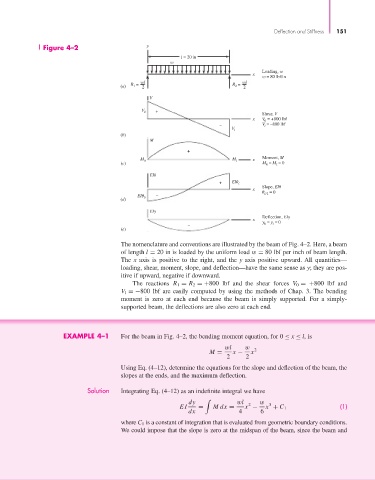
The nomenclature and conventions are illustrated by the beam of Fig. 4–2. Here, a beam
of length l = 20 in is loaded by the uniform load w = 80 lbf per inch of beam length.
The x axis is positive to the right, and the y axis positive upward. All quantities—
loading, shear, moment, slope, and deflection—have the same sense as y; they are pos-
itive if upward, negative if downward.
The reactions R 1 = R 2 =+800 lbf and the shear forces V 0 =+800 lbf and
V l =−800 lbf are easily computed by using the methods of Chap. 3. The bending
moment is zero at each end because the beam is simply supported. For a simply-
supported beam, the deflections are also zero at each end.
EXAMPLE 4–1 For the beam in Fig. 4–2, the bending moment equation, for 0 ≤ x ≤ l, is
wl w 2
M = x − x
2 2
Using Eq. (4–12), determine the equations for the slope and deflection of the beam, the
slopes at the ends, and the maximum deflection.
Solution Integrating Eq. (4–12) as an indefinite integral we have
dy wl 2 w 3
EI = Mdx = x − x + C 1 (1)
dx 4 6
where C 1 is a constant of integration that is evaluated from geometric boundary conditions.
We could impose that the slope is zero at the midspan of the beam, since the beam and