
Page 180 - Shigley's Mechanical Engineering Design
P. 180
bud29281_ch04_147-211.qxd 11/27/09 2:55PM Page 155 ntt 203:MHDQ196:bud29281:0073529281:bud29281_pagefiles:
Deflection and Stiffness 155
Sometimes it may not be obvious that we can use superposition with the tables at
hand, as demonstrated in the next example.
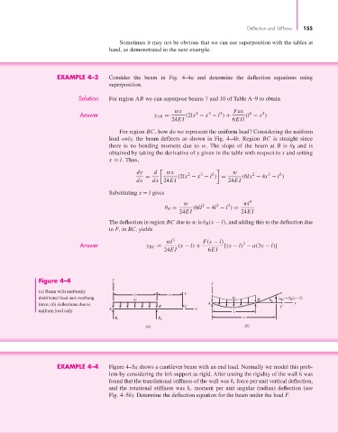
EXAMPLE 4–3 Consider the beam in Fig. 4–4a and determine the deflection equations using
superposition.
Solution For region AB we can superpose beams 7 and 10 of Table A–9 to obtain
wx Fax
2
2
3
3
2
Answer y AB = (2lx − x − l ) + (l − x )
24EI 6EIl
For region BC, how do we represent the uniform load? Considering the uniform
load only, the beam deflects as shown in Fig. 4–4b. Region BC is straight since
there is no bending moment due to w. The slope of the beam at B is θ B and is
obtained by taking the derivative of y given in the table with respect to x and setting
x = l. Thus,
dy d wx 2 3 3 w 2 3 3
= (2lx − x − l ) = (6lx − 4x − l )
dx dx 24EI 24EI
Substituting x = l gives
w 2 3 3 wl 3
θ B = (6ll − 4l − l ) =
24EI 24EI
The deflection in region BC due to w is θ B (x − l), and adding this to the deflection due
to F, in BC, yields
wl 3 F(x − l)
Answer y BC = (x − l) + [(x − l) − a(3x − l)]
2
24EI 6EI
Figure 4–4 y
y
(a) Beam with uniformly
l a F
distributed load and overhang w w B y = (x – l)
B
BC
force; (b) deflections due to B C A B C x
uniform load only. A x l
R 1 R 2 x
(a) (b)
EXAMPLE 4–4 Figure 4–5a shows a cantilever beam with an end load. Normally we model this prob-
lem by considering the left support as rigid. After testing the rigidity of the wall it was
found that the translational stiffness of the wall was k t force per unit vertical deflection,
and the rotational stiffness was k r moment per unit angular (radian) deflection (see
Fig. 4–5b). Determine the deflection equation for the beam under the load F.