
Page 183 - Shigley's Mechanical Engineering Design
P. 183
bud29281_ch04_147-211.qxd 11/27/2009 7:54 pm Page 158 pinnacle s-171:Desktop Folder:Temp Work:Don't Delete (Jobs):MHDQ196/Budynas:
158 Mechanical Engineering Design
Finally, substituting C 1 and C 2 in Eq. (5) and simplifying produces
F 2 2 2 3
y = [bx(x + b − l ) − l x − a ] (6)
6EIl
Comparing Eq. (6) with the two deflection equations for beam 6 in Table A–9, we note
that the use of singularity functions enables us to express the deflection equation with
a single equation.
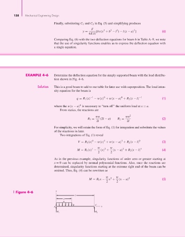
EXAMPLE 4–6 Determine the deflection equation for the simply supported beam with the load distribu-
tion shown in Fig. 4–6.
Solution This is a good beam to add to our table for later use with superposition. The load inten-
sity equation for the beam is
−1 0 0 −1
q = R 1 x − w x + w x − a + R 2 x − l (1)
0
where the w x − a is necessary to “turn off” the uniform load at x = a.
From statics, the reactions are
wa wa 2
R 1 = (2l − a) R 2 = (2)
2l 2l
For simplicity, we will retain the form of Eq. (1) for integration and substitute the values
of the reactions in later.
Two integrations of Eq. (1) reveal
0 1 1 0
V = R 1 x − w x + w x − a + R 2 x − l (3)
w w
1 2 2 1
M = R 1 x − x + x − a + R 2 x − l (4)
2 2
As in the previous example, singularity functions of order zero or greater starting at
x = 0 can be replaced by normal polynomial functions. Also, once the reactions are
determined, singularity functions starting at the extreme right end of the beam can be
omitted. Thus, Eq. (4) can be rewritten as
w 2 w 2
M = R 1 x − x + x − a (5)
2 2
Figure 4–6 y
l
a
w
B C
A x
R 1 R 2