
Page 181 - Shigley's Mechanical Engineering Design
P. 181
bud29281_ch04_147-211.qxd 11/27/09 2:55PM Page 156 ntt 203:MHDQ196:bud29281:0073529281:bud29281_pagefiles:
156 Mechanical Engineering Design
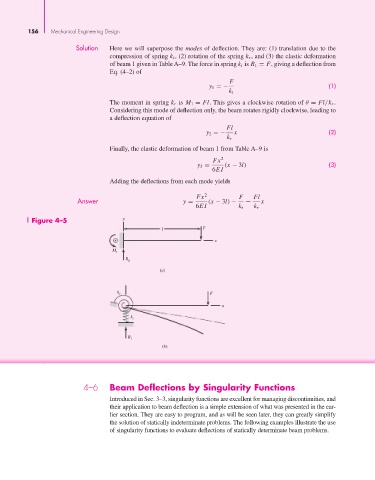
Solution Here we will superpose the modes of deflection. They are: (1) translation due to the
compression of spring k t , (2) rotation of the spring k r , and (3) the elastic deformation
of beam 1 given in Table A–9. The force in spring k t is R 1 = F, giving a deflection from
Eq. (4–2) of
F
y 1 =− (1)
k t
The moment in spring k r is M 1 = Fl. This gives a clockwise rotation of θ = Fl/k r .
Considering this mode of deflection only, the beam rotates rigidly clockwise, leading to
a deflection equation of
Fl
y 2 =− x (2)
k r
Finally, the elastic deformation of beam 1 from Table A–9 is
Fx 2
y 3 = (x − 3l) (3)
6EI
Adding the deflections from each mode yields
Fx 2 F Fl
Answer y = (x − 3l) − − x
6EI k t k r
Figure 4–5 y
l F
x
M 1
R
1
(a)
k r F
x
k t
R
1
(b)
4–6 Beam Deflections by Singularity Functions
Introduced in Sec. 3–3, singularity functions are excellent for managing discontinuities, and
their application to beam deflection is a simple extension of what was presented in the ear-
lier section. They are easy to program, and as will be seen later, they can greatly simplify
the solution of statically indeterminate problems. The following examples illustrate the use
of singularity functions to evaluate deflections of statically determinate beam problems.