Page 186 - Shigley's Mechanical Engineering Design
P. 186

bud29281_ch04_147-211.qxd  11/27/09  2:55PM  Page 161 ntt 203:MHDQ196:bud29281:0073529281:bud29281_pagefiles:


                                                                                              Deflection and Stiffness  161
                                                                            2
                                                                                                               6
                                               Solving, gives C 1 =−50 565 lbf/in . Thus, Eq. (4) becomes, with E = 30(10) psi,
                                                                1          3            3                2
                                                          y =       (241.5x − 402.4 x − 8  − 2 555.9 x − 8.5
                                                                   6
                                                              30(10 )                                             (5)
                                                                            3
                                                              + 74.08 x − 8.5  − 50 565x)
                                               When using a spreadsheet, program the following equations:
                                                            1         3
                                                     y =        (241.5x − 50 565x)                0 ≤ x ≤ 8in
                                                              6
                                                         30(10 )
                                                            1         3             3
                                                     y =        [241.5x − 402.4(x − 8) − 50 565x]  8 ≤ x ≤ 8.5in
                                                              6
                                                         30(10 )
                                                            1         3             3                2
                                                     y =        [241.5x − 402.4 (x − 8) − 2 555.9 (x − 8.5)
                                                              6
                                                         30(10 )
                                                                       3
                                                         + 74.08 (x − 8.5) − 50 565x]             8.5 ≤ x ≤ 20 in
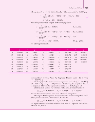
                                               The following table results.


                       x         y        x        y         x         y         x         y         x         y
                        0      0.000000  4.5     0.006851     9     0.009335    13.5    0.007001     18     0.002377
                       0.5    0.000842     5     0.007421    9.5    0.009238     14     0.006571    18.5    0.001790
                        1     0.001677   5.5     0.007931    10     0.009096    14.5    0.006116     19     0.001197
                       1.5    0.002501     6     0.008374   10.5    0.008909     15     0.005636    19.5    0.000600
                        2     0.003307   6.5     0.008745    11     0.008682    15.5    0.005134     20     0.000000
                       2.5    0.004088     7     0.009037   11.5    0.008415     16     0.004613
                        3     0.004839   7.5     0.009245    12     0.008112    16.5    0.004075
                       3.5    0.005554     8     0.009362   12.5    0.007773     17     0.003521
                        4     0.006227   8.5     0.009385    13     0.007403    17.5    0.002954


                                               where x and y are in inches. We see that the greatest deflection is at x = 8.5 in, where
                                               y =−0.009385 in.
                                                                                                                  −3
                                                  Substituting C 1 into Eq. (3) the slopes at the supports are found to be θ A = 1.686(10 )
                                                                              −3
                                               rad = 0.09657 deg, and θ F = 1.198(10 ) rad = 0.06864 deg. You might think these to
                                               be insignificant deflections, but as you will see in Chap. 7, on shafts, they are not.
                                                  A finite-element analysis was performed for the same model and resulted in
                                                       y| x=8.5in =−0.009380 in  θ A =−0.09653 ◦  θ F = 0.06868 ◦
                                               Virtually the same answer save some round-off error in the equations.
                                                  If the steps of the bearings were incorporated into the model, more equations result,
                                               but the process is the same. The solution to this model is

                                                       y| x=8.5in =−0.009387 in  θ A =−0.09763 ◦  θ F = 0.06973 ◦
                                               The largest difference between the models is of the order of 1.5 percent. Thus the sim-
                                               plification was justified.
   181   182   183   184   185   186   187   188   189   190   191