
Page 171 - Shigley's Mechanical Engineering Design
P. 171
bud29281_ch03_071-146.qxd 11/25/09 4:55PM Page 146 ntt 203:MHDQ196:bud29281:0073529281:bud29281_pagefiles:
146 Mechanical Engineering Design
3–133 Two carbon steel balls, each 30 mm in diameter, are pressed together by a force F. In terms of
the force F, find the maximum values of the principal stress, and the maximum shear stress, in
MPa.
3–134 A carbon steel ball with 25-mm diameter is pressed together with an aluminum ball with a
40-mm diameter by a force of 10 N. Determine the maximum shear stress, and the depth at
which it will occur for the aluminum ball. Assume Fig. 3–37, which is based on a typical
Poisson’s ratio of 0.3, is applicable to estimate the depth at which the maximum shear stress
occurs for these materials.
3–135 Repeat Prob. 3–134 but determine the maximum shear stress and depth for the steel ball.
3–136 A carbon steel ball with a 30-mm diameter is pressed against a flat carbon steel plate with a force
of 20 N. Determine the maximum shear stress, and the depth in the plate at which it will occur.
3–137 An AISI 1018 steel ball with 1-in diameter is used as a roller between a flat plate made from 2024
T3 aluminum and a flat table surface made from ASTM No. 30 gray cast iron. Determine the
maximum amount of weight that can be stacked on the aluminum plate without exceeding a max-
imum shear stress of 20 kpsi in any of the three pieces. Assume Fig. 3–37, which is based on a
typical Poisson’s ratio of 0.3, is applicable to estimate the depth at which the maximum shear
stress occurs for these materials.
3–138 An aluminum alloy cylindrical roller with diameter 1.25 in and length 2 in rolls on the inside of
a cast-iron ring having an inside radius of 6 in, which is 2 in thick. Find the maximum contact
force F that can be used if the shear stress is not to exceed 4000 psi.
3–139 A pair of mating steel spur gears with a 0.75-in face width transmits a load of 40 lbf. For
estimating the contact stresses, make the simplifying assumption that the teeth profiles can be
treated as cylindrical with instantaneous radii at the contact point of interest of 0.47 in and
0.62 in, respectively. Estimate the maximum contact pressure and the maximum shear stress
experienced by either gear.
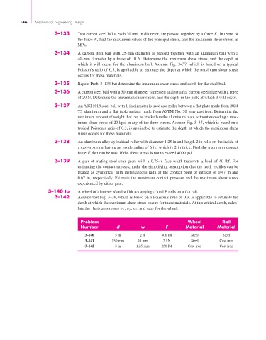
3–140 to A wheel of diameter d and width w carrying a load F rolls on a flat rail.
3–142 Assume that Fig. 3–39, which is based on a Poisson’s ratio of 0.3, is applicable to estimate the
depth at which the maximum shear stress occurs for these materials. At this critical depth, calcu-
late the Hertzian stresses σ x , σ y , σ z , and τ max for the wheel.
Problem Wheel Rail
Number d w F Material Material
3–140 5 in 2 in 600 lbf Steel Steel
3–141 150 mm 40 mm 2 kN Steel Cast iron
3–142 3 in 1.25 mm 250 lbf Cast iron Cast iron