
Page 170 - Shigley's Mechanical Engineering Design
P. 170
bud29281_ch03_071-146.qxd 11/25/09 4:55PM Page 145 ntt 203:MHDQ196:bud29281:0073529281:bud29281_pagefiles:
Load and Stress Analysis 145
3–128 Repeat Prob. 3–126 with a bend radius of in.
1
4
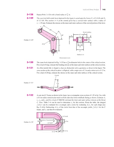
3–129 The cast-iron bell-crank lever depicted in the figure is acted upon by forces F 1 of 2.4 kN and F 2
of 3.2 kN. The section A–A at the central pivot has a curved inner surface with a radius of
r i = 25 mm. Estimate the stresses at the inner and outer surfaces of the curved portion of the lever.
F
1
200
Nylon bushing
60° 87
25
A
Problem 3–129 9
A
25 R.
150 31
28
47
F 2
Section A–A
Dimensions in mm
3
3–130 The crane hook depicted in Fig. 3–35 has a -in-diameter hole in the center of the critical section.
4
For a load of 6 kip, estimate the bending stresses at the inner and outer surfaces at the critical section.
3–131 An offset tensile link is shaped to clear an obstruction with a geometry as shown in the figure. The
cross section at the critical location is elliptical, with a major axis of 3 in and a minor axis of 1.5 in.
For a load of 20 kip, estimate the stresses at the inner and outer surfaces of the critical section.
12-in R.
Problem 3–131 9 in
3–132 A cast-steel C frame as shown in the figure has a rectangular cross section of 1.25 in by 2 in, with
a 0.5-in-radius semicircular notch on both sides that forms midflank fluting as shown. Estimate A,
r c , r n , and e, and for a load of 2000 lbf, estimate the inner and outer surface stresses at the throat
C. Note: Table 3–4 can be used to determine r n for this section. From the table, the integral
dA/r can be evaluated for a rectangle and a circle by evaluating A/r n for each shape [see
Eq. (3–64)]. Subtracting A/r n of the circle from that of the rectangle yields dA/r for the C
frame, and r n can then be evaluated.
0.5-in R.
4.5 in
2000 lbf 1.25 in
Problem 3–132
1.25-in R.
0.5 in
0.5 in